Device for processing rotary part by forming electrode air plasma

A plasma and forming electrode technology, applied in electrical components, plasma welding equipment, metal processing equipment, etc., can solve problems such as shortening the processing cycle, and achieve the effects of overcoming the long processing cycle, reducing costs, and simplifying the structure

Inactive Publication Date: 2013-08-07
HARBIN INST OF TECH
View PDF4 Cites 2 Cited by
  • Summary
  • Abstract
  • Description
  • Claims
  • Application Information

AI Technical Summary

Problems solved by technology

[0003] The purpose of the present invention is to provide a device for processing rotary parts with forming electrode atmospheric plasma. In order to solve the processing efficiency and quality problems of high-precision rotary parts, the processing cycle is greatly shortened, and the processing cost is effectively reduced to meet the needs of aerospace, energy and other fields. The question of the demand for such parts

Method used


Image

  • Device for processing rotary part by forming electrode air plasma
  • Device for processing rotary part by forming electrode air plasma
  • Device for processing rotary part by forming electrode air plasma

Examples


specific Embodiment approach 1

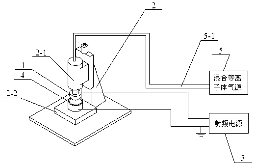
[0015] Specific implementation mode one: combine figure 1 , figure 2 As shown, this embodiment consists of a rotating forming electrode 1, a lifting device 2, a radio frequency power supply 3, and a mixed plasma gas source 5;

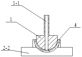
[0016] The upper end surface of the rotating forming electrode 1 is insulated and connected to the vertical movement working shaft 2-1 of the lifting device 2, and the center of the rotating forming electrode 1 has an air outlet 1-1; when the inner surface is processed, the working of the rotating forming electrode 1 The diameter of the surface needs to be 5mm-15mm smaller than the diameter of the inner surface of the part 4 to be processed, and the diameter of the working surface of the rotating forming electrode 1 needs to be 5mm-15mm larger than the diameter of the outer surface of the part 4 to be processed when processing the outer surface; The air outlet 1-1 communicates with the mixed plasma gas source 5 through the gas pipe 5-1; the rotating ...

specific Embodiment approach 2

[0022] Specific implementation mode two: combination figure 2 As shown, the difference between this embodiment and the first embodiment is that the transfer-shaped electrode 1 is circular and convex. Other compositions and connections are the same as in the first embodiment.

specific Embodiment approach 3

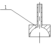
[0023] Specific implementation mode three: combination image 3 As shown, the difference between this embodiment and the first embodiment is that the transfer-shaped electrode 1 is circular and concave. Other compositions and connections are the same as in the first embodiment.


PUM


Abstract

The invention relates to a device for processing a rotary part by forming electrode air plasma, and belongs to the technical field of the processing of a silicon carbide or melted quartz type silicon-based material rotary part by plasma, which aims at solving the problems existing in the processing efficiency and quality of the high-precision rotary part. The upper end surface of a rotary forming electrode is connected with a rotary shaft in an insulating way, and the center of the rotary forming electrode is provided with an air outlet hole. When the inner surface is processed, the diameter of the working surface of the rotary forming electrode is 5 to 15mm smaller than the diameter of the inner surface of a to-be-processed part. When the outer surface is processed, the diameter of the working surface of the rotary forming electrode is 5 to 15mm larger than the diameter of the outer surface of the to-be-processed part. The rotary forming electrode is arranged near the to-be-processed surface of the to-be-processed part, and a certain discharging gap is maintained between the rotary forming electrode and the to-be-processed part. The device has the advantages that the simple and reasonable structure is adopted, and the air plasma processing method is utilized, so the removal of full-surface reflection is realized; and meanwhile, the problems existing in the processing efficiency and quality of the high-precision rotary part are solved.

Description

technical field [0001] The invention belongs to the technical field of plasma processing silicon carbide or fused quartz and other silicon-based material rotary parts. Background technique [0002] In recent years, the demand for high-precision rotary parts, such as hemispherical gyro resonators, large-curvature aspheric optical lenses, and light-concentrating aspheric lenses, has become increasingly strong in the fields of aerospace, military, energy, and chip manufacturing. Surface requirements are becoming more and more demanding. The processed surface needs to reach the surface roughness value of Ra 1nm, and strictly limit the surface and subsurface damage of the material caused by the processing process. Because most of these parts are brittle and hard materials such as silicon carbide and fused quartz, the traditional ultra-precision grinding and subsequent polishing process has problems such as long processing cycle, damage to the processed surface and sub-surface, a...

Claims


Application Information

Patent Timeline
Patent Type & Authority Applications(China)
IPC IPC(8): H01J37/32B23K10/00
Inventor 王波李铎姚英学金会良李娜辛强金江
Owner HARBIN INST OF TECH
Why Eureka
Try Eureka