Metal plastic extrusion forming host machine

A technology of extrusion forming and main engine, applied in the field of metal plastic extrusion forming equipment, can solve the problems of large equipment investment, long extrusion processing line, no mold, etc., meet high material requirements, solve cooling and lubrication problems, and reduce production cost effect

Inactive Publication Date: 2015-03-25
ZHUZHOU WENJIA IND
View PDF9 Cites 0 Cited by
  • Summary
  • Abstract
  • Description
  • Claims
  • Application Information

AI Technical Summary

Problems solved by technology

However, due to the limitation of current equipment (mainly friction presses, mechanical presses, flat forging machines, etc., which cannot process parts with large deformation due to their low energy supply) and mold materials, this technology cannot be used. widely used
[0003] At present, there are many technical bottlenecks in the application of precision forging technology and extrusion molding equipment at home and abroad, so that the technology cannot be fully developed
[0004] First, the energy supply is not large enough to meet the energy demand for the deformation of complex parts. Although the force (tonnage) of a single device is sufficient, the energy supplied is not enough, and multiple extrusions of multiple devices are required to meet the requirements. The geometric deformation of parts will inevitably lead to large investment in equipment and waste of resources, which will affect the widespread promotion and application of this technology. Therefore, general industrial and mining enterprises dare not enter
[0005] Second, the mold has no versatility and interchangeability, resulting in a product specification requiring a pair of molds, so that the equipment is only suitable for batch production, and the applicable area is narrow
[0006] Third, the extrusion processing production line is long, requiring multiple sets of equipment and 5 to 20 production workers, the production site is large, the working environment is harsh, and the production cost is high

Method used


Image

  • Metal plastic extrusion forming host machine
  • Metal plastic extrusion forming host machine

Examples


Embodiment Construction

[0026] The present invention will be further described below in conjunction with the accompanying drawings and embodiments.

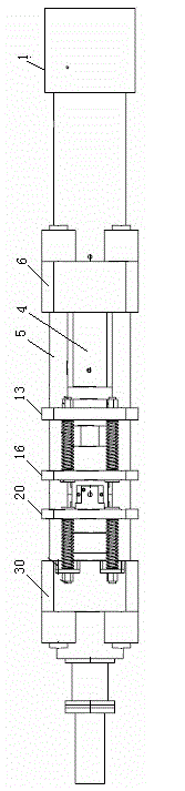
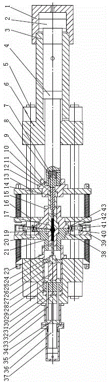
[0027]Referring to the accompanying drawings, this embodiment includes a main engine frame, the main engine frame is composed of an upper cylinder beam 6, a lower cylinder beam 30, and a column 5 through nuts, and the column 5 is provided with an upper moving beam 13, a middle moving beam 16, a lower Moving beam 20, said upper cylinder beam 6 is provided with main oil cylinder 3, said main oil cylinder 3 is provided with main piston rod 4, said main piston rod 4 is provided with functional plunger oil cylinder and oil port, said function The plunger cylinder is provided with a functional plunger 7 and a functional dowel 8, and the main cylinder 3 is provided with a booster plunger cylinder 1, and the booster plunger cylinder 1 is connected to the main cylinder 3, and the booster cylinder 3 is connected to the main cylinder 3. A booster plunger 2 is arra...


PUM

PropertyMeasurementUnit
surface roughnessaaaaaaaaaa

Abstract

The invention discloses a metal plastic extrusion forming host machine, which comprises a host machine framework, wherein the host machine framework consists of an upper cylinder beam, a lower cylinder beam and a vertical column, wherein the vertical column is provided with an upper movable beam, a middle movable beam and a lower movable beam; a main oil cylinder is arranged in the upper cylinder beam; a main piston rod is arranged in the main oil cylinder; the main oil cylinder is provided with a boosting plunger oil cylinder; a boosting plunger is arranged in the boosting plunger oil cylinder; an upper die holder is arranged on the upper movable beam; an upper punch column base and an upper punch are arranged in the upper die holder; an upper stress ring female die is arranged on the middle movable beam; an upper die core is arranged in the upper stress ring female die; the lower movable beam is provided with a lower stress ring female die; a low die core is arranged in the lower stress ring female die; the lower movable beam is connected with a limiting spring base on the lower cylinder beam through a limiting rod, a limiting spring and a limiting nut; mechanical locks are arranged outside the upper stress ring female die and the lower stress ring female die; a lower die barrel and a discharging mechanism are arranged in the lower cylinder beam; and a lower punch is arranged on the discharging mechanism. The metal plastic extrusion forming host has the advantages of simple structure, capability of meeting the requirement of energy needed by the deformation of complex parts, and wide application range.

Description

technical field [0001] The invention relates to a metal plastic extrusion forming equipment, in particular to a main machine of the metal plastic extrusion forming equipment. Background technique [0002] Metal extrusion technology is a processing technology with less and no cutting pressure. It is an important branch of forging processing technology and an important part of advanced manufacturing technology. Compared with traditional manufacturing technology, it has the advantages of saving materials and energy, reducing processing procedures and equipment, improving production efficiency and product quality, and reducing production costs. However, due to the limitation of current equipment (mainly friction presses, mechanical presses, flat forging machines, etc., which cannot process parts with large deformation due to their low energy supply) and mold materials, this technology cannot be used. widely used. [0003] At present, there are many technical bottlenecks in the...

Claims


Application Information

Patent Timeline
Patent Type & Authority Patents(China)
IPC IPC(8): B21C23/21B21C35/02
Inventor 龙西新
Owner ZHUZHOU WENJIA IND
Why Eureka
Try Eureka