
High refraction and low dispersion optical glass and manufacturing method thereof

An optical glass and manufacturing method technology, applied in glass manufacturing equipment, glass pressing, manufacturing tools, etc., can solve the problems of high price, reduced transmittance, high cost, etc., and achieve low-cost operation and mass production, good resistance Devitrification, good quality effect

Active Publication Date: 2016-01-13
CHENGDU UNITE OPTOELECTRONICS TECH CO LTD
View PDF7 Cites 0 Cited by
  • Summary
  • Abstract
  • Description
  • Claims
  • Application Information

AI Technical Summary

Problems solved by technology

[0004] There are also a large amount of expensive GeO2 components introduced to maintain the stability of the glass while greatly increasing the refractive index, such as the patent document: CN1955128A, and the high cost is impossible to achieve quantitative production
[0005] Another example is patent literature: CN101289276A, CN101012103A, its refractive index (nd) also reaches more than 1.94, but the Abbe number (vd) is less than 29, only with the comparison of the same refractive index, the Abbe number (vd) is also less than the scope of the present invention The optical constants cannot meet the design requirements of the current new SLR, camera zoom optical system and digital camera optical system
[0006] Furthermore, for this kind of ultra-high refractive index glass, as the refractive index increases, the coloring of the glass will also deepen, and the transmittance will also decrease.
In particular, when using glass that tends to become darker in color, the sensitivity to blue light on the short-wavelength side of the primary color in the optical imaging system of the camera will decrease, which will seriously affect the clarity of the imaging quality, especially the imaging of the zoom optical system of the camera. quality

Method used


Image

  • High refraction and low dispersion optical glass and manufacturing method thereof
  • High refraction and low dispersion optical glass and manufacturing method thereof
  • High refraction and low dispersion optical glass and manufacturing method thereof

Examples


Embodiment 1

[0094] Embodiment 1 The properties of the optical glass of the present invention

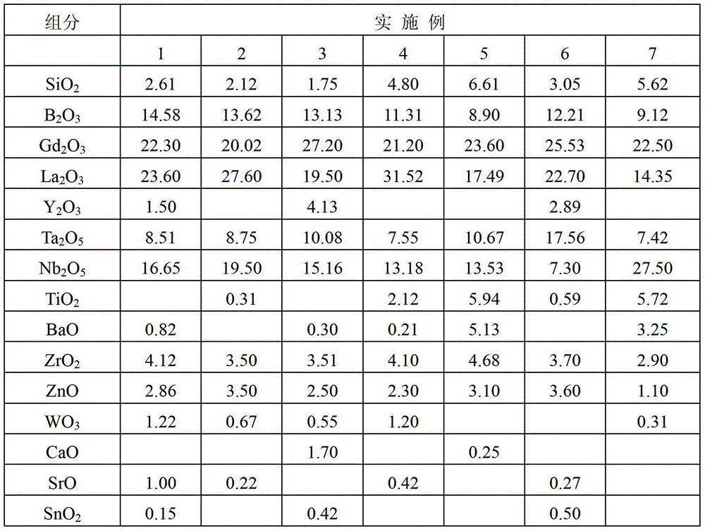
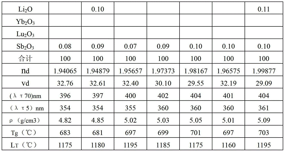
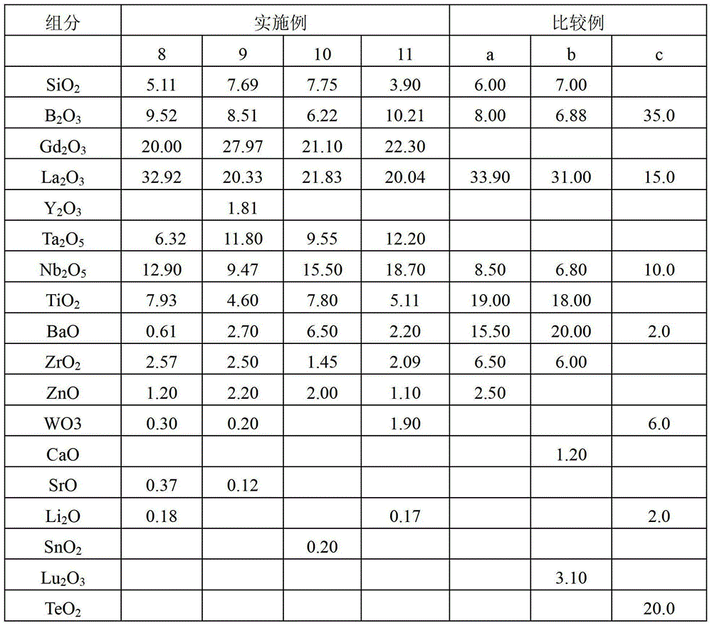
[0095] Tables 1 and 2 show the glass composition of Examples No. 1 to No. 11 of the optical glass of the present invention and the composition of Comparative Examples No. 1 to No. c of the same type of high refraction glass as the glass of the present invention. The optical glass obtained by annealing at -4.0 / h and cooling in each example and comparative example is measured as follows, the refractive index (nd), Abbe number (vd), internal transmission (λτ70) and (λτ5), The measurement results of density (ρ), transition temperature (Tg) and liquidus temperature (LT) are given in Tables 1 and 2.

[0096] The corresponding raw materials such as various oxides, carbonates and nitrates of the raw materials of each component are weighed and mixed according to the composition of each embodiment and comparative example to make a batch, which is added to a platinum container or After melting, stirring, ...


PUM

PropertyMeasurementUnit
densityaaaaaaaaaa
transition temperatureaaaaaaaaaa
liquidus temperatureaaaaaaaaaa

Abstract

Disclosed are a high-refraction and low-dispersion optical glass containing no GeO2 or TeO2 components, and a preparation method therefor. The optical glass comprises, based on the weight percentages of the oxides, at least one of CaO, SrO and BaO, 1-10% of SiO2, 5-18% of B2O3, the total amount of (SiO2+B2O3) being less than 20%, 20-30% of Gd2O3,12-35% of La2O3, 0-8% of Y2O3, the total amount of (Gd2O3+La2O3+Y2O3) being less than 58%, 5-20% of Ta2O5,5-32% of Nb2O5, the total amount of (Ta2O5+Nb2O5) being 17-38%, 0-8% of TiO2, more than 0 but less than 7% of ZrO2, more than 0 but less than 6% of ZnO, 0-5% of WO3, 0-8% of BaO, 0-4% of CaO, 0-4% of SrO, 0-2% of SnO2, 0-2% of Li2O, and 0-1% of Sb2O3. The optical glass has the optical constants of a refractive index (nd) of above 1.94, and an Abbe number (Vd) of above 29 but below 33; the upper limit of the internal transmittance formula (I) λτ70 of the glass is 405 nm or lower; and the liquidus temperature is lower than 1210°C.

Description

technical field [0001] The invention relates to an optical glass with high refraction and low dispersion and a method for manufacturing the optical glass. More specifically, the present invention provides an optical glass having a refractive index of 1.94 or more, an Abbe number (vd) of 29 or more but less than 33 optical constants, high transmission and good stability. The blank of the optical glass can be used for secondary hot pressing and made into optical elements of different shapes. Background technique [0002] In recent years, with the rapid popularization of single-lens reflex cameras and video cameras, it is also widely used as an optical system in a single-lens reflex camera, especially as an optical zoom system for such cameras and video cameras. As the glass with high refractive index and low dispersion used in its optical system, it not only needs to meet the design requirements of the optical system of high-performance SLR cameras, video cameras and digital ...

Claims


Application Information

Patent Timeline
Patent Type & Authority Patents(China)
IPC IPC(8): C03C3/068C03C4/00C03B11/00
CPCC03C3/068
Inventor 王自力黄俊
Owner CHENGDU UNITE OPTOELECTRONICS TECH CO LTD
Learn More