
Novel fiber bragg grating demodulation method and system thereof based on multi-longitudinal mode F-P laser device

A fiber grating demodulation, fiber grating technology, applied in instruments, scientific instruments, thermometers with physical/chemical changes, etc., can solve the problems of low response speed, expensive narrowband filters, increase demodulation cost, etc., and achieve real-time measurement. , Not easy to electromagnetic interference, convenient multi-grating multiplexing demodulation effect

Active Publication Date: 2013-08-14
黎敏
View PDF11 Cites 23 Cited by
  • Summary
  • Abstract
  • Description
  • Claims
  • Application Information

AI Technical Summary

Problems solved by technology

However, there are two main problems in the above-mentioned demodulation methods: 1. The use of expensive broadband light source and narrow-band filter greatly increases the cost of demodulation; 2. The inherent electromechanical modulation structure of the narrow-band filter makes the response of the system Low speed, generally below 200Hz, only suitable for detection of low frequency signals

Method used


Image

  • Novel fiber bragg grating demodulation method and system thereof based on multi-longitudinal mode F-P laser device
  • Novel fiber bragg grating demodulation method and system thereof based on multi-longitudinal mode F-P laser device
  • Novel fiber bragg grating demodulation method and system thereof based on multi-longitudinal mode F-P laser device

Examples


Embodiment Construction

[0034] The technical solution of the present invention will be described in further detail below in conjunction with the accompanying drawings and embodiments.

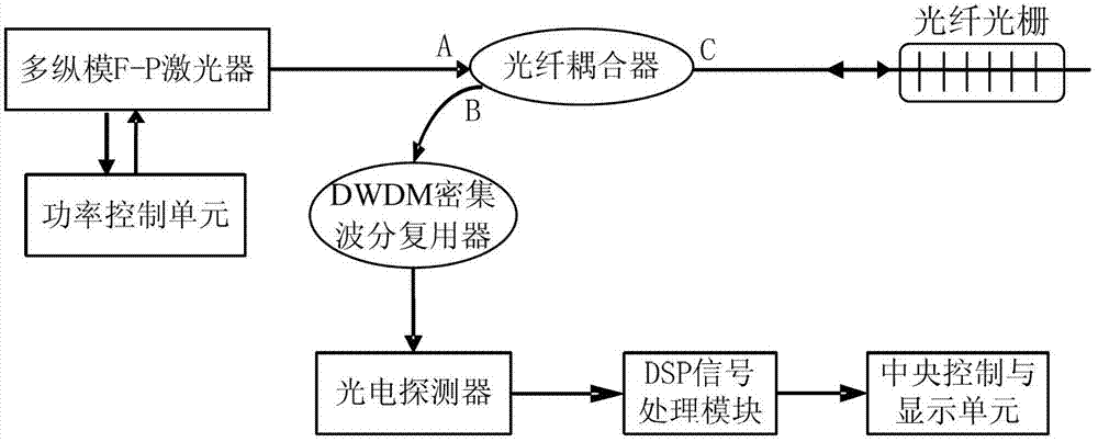
[0035] refer to figure 1 As shown, the fiber grating demodulation system based on multi-longitudinal mode F-P lasers of the present invention includes multi-longitudinal mode F-P lasers, fiber couplers, fiber gratings, DWDM dense wavelength division multiplexers, photodetectors, DSP signal processing module, a central control and display unit, and a power control unit connected to the multi-longitudinal mode F-P laser, the output end of the multi-longitudinal mode F-P laser is connected to the input port A of the fiber coupler, and the output port C of the fiber coupler is connected to the fiber grating Connection, the input port B of the fiber coupler is connected with the input end of the DWDM dense wavelength division multiplexer to form the optical channel of the signal, and the output end of the DWDM dense wavele...


PUM

PropertyMeasurementUnit
wavelengthaaaaaaaaaa
widthaaaaaaaaaa

Abstract

The invention provides a novel fiber bragg grating demodulation method and a system thereof based on a multi-longitudinal mode F-P laser device. The system comprises the multi-longitudinal mode F-P laser device, an optical fiber coupler, fiber bragg gratings, a DWDM (dense wavelength division multiplexing) device, a photoelectric detector, a DSP (digital signal processor) module, a central control and display unit and a power control unit which is connected with the multi-longitudinal mode F-P laser device, wherein lasers sent by the multi-longitudinal mode F-P laser device enter the fiber bragg gratings through the optical fiber coupler; signals output by the fiber bragg gratings enter the DWDM device with matched wavelengths after transmitted by optical fibers, and output optical signals are received by the photoelectric detector and converted into voltage signals; and the voltage signals are calculated and controlled by the DSP signal processing module, so that demodulation signals are acquired; and the demodulation signals are sent to the central control and display unit for judgment and operation and are provided for peripheral equipment for display through a serial port. The method and the system have the benefits as follows: the multi-longitudinal mode F-P laser device is matched with the DSP signal processing module, so that high-speed dynamic demodulation and multiplex of grating signals are realized, and the demodulation cost is reduced.

Description

technical field [0001] The invention relates to a method and device for dynamic demodulation of fiber gratings, in particular to a novel fiber grating demodulation method and system based on multi-longitudinal mode F-P lasers. Background technique [0002] Fiber Bragg grating sensor is a new type of sensor that has been studied more in recent years. It is famous for its extremely high sensitivity, intrinsic safety, anti-electromagnetic interference, high dielectric strength, and small size. At present, the main obstacle restricting the application of FBG sensors is the high cost of demodulation of sensing signals. Existing demodulation methods can be generally divided into two categories: wide-spectrum light source + narrow-band filter and narrow-band tunable light source demodulation method. Because the demodulation method of narrowband tunable light source has disadvantages in terms of stability, tunable range, modulation difficulty and price; therefore, the demodulation ...

Claims


Application Information

Patent Timeline
Patent Type & Authority Applications(China)
IPC IPC(8): G01D5/26G01K11/32G01K11/3206
Inventor 黎敏舒卓郭晶晶郑光辉李玉林
Owner 黎敏
Learn More