Optical fiber collimator and production method thereof

A technology of fiber collimator and manufacturing method, which is applied in optics, instruments, optical components, etc., can solve the problems of difficult process, large return loss of collimator, low production efficiency, etc., and achieve simple assembly process, low echo Effect of low loss and few parts

Active Publication Date: 2013-08-14
深圳市天阳谷科技发展有限公司
View PDF4 Cites 9 Cited by
  • Summary
  • Abstract
  • Description
  • Claims
  • Application Information

AI Technical Summary

Problems solved by technology

The assembly structure of the optical fiber collimator 10 has the following problems: both the self-focusing lens and the capillary need to be ground and polished on the end face, which takes a long time to process, the process is difficult, and it is difficult to ensure the yield rate, which is accompanied by relatively low production efficiency; There are many parts required for assembly, and the assembly process is cumbersome, and it must go through more than 3 times of matching and bonding processes; the central axis of the capillary and the core axis of the self-focusing lens must be coaxial, and in order to achieve the best optical performance, To ensure a high degree of coaxiality, it is necessary to repeatedly adjust the positions of the anti-reflection films 12a and 14a. The adjustment process takes a long time and requires high technical proficiency of the operator; the return loss of the collimator is large: the light passes through the capillary and the anti-reflection of the end surface of the capillary The self-focusing lens and the anti-reflection film on the end face of the self-focusing lens still have part of the light reflected on the interface, and the reflected light will interfere with the resonant light in the laser resonator cavity, causing the laser to be unstable. Return loss is too large
This optical fiber collimator 20 has the following problems: the rod lens 21 needs to grind and polish the end face, which takes a long time, and causes the reduction of yield and production efficiency; Therefore, before the final completion, cumbersome optical path adjustment is required, which is time-consuming and labor-intensive; the return loss (RL) of the collimator is large: because the light passes through dozens of layers such as the end face of the optical fiber 22 and the optical adhesive 23 The reflective film 21b composed of a dielectric film will always have part of the light reflected on its interface. Even if an anti-reflection film is coated on the interface, the reflected light will interfere with the resonant light in the laser resonator, making the laser unstable. Make the collimator return loss (RL) large
The structure of the collimator 20 is relatively fixed and cannot be further reduced in size and integrated

Method used


Image

  • Optical fiber collimator and production method thereof
  • Optical fiber collimator and production method thereof
  • Optical fiber collimator and production method thereof

Examples


Embodiment 1

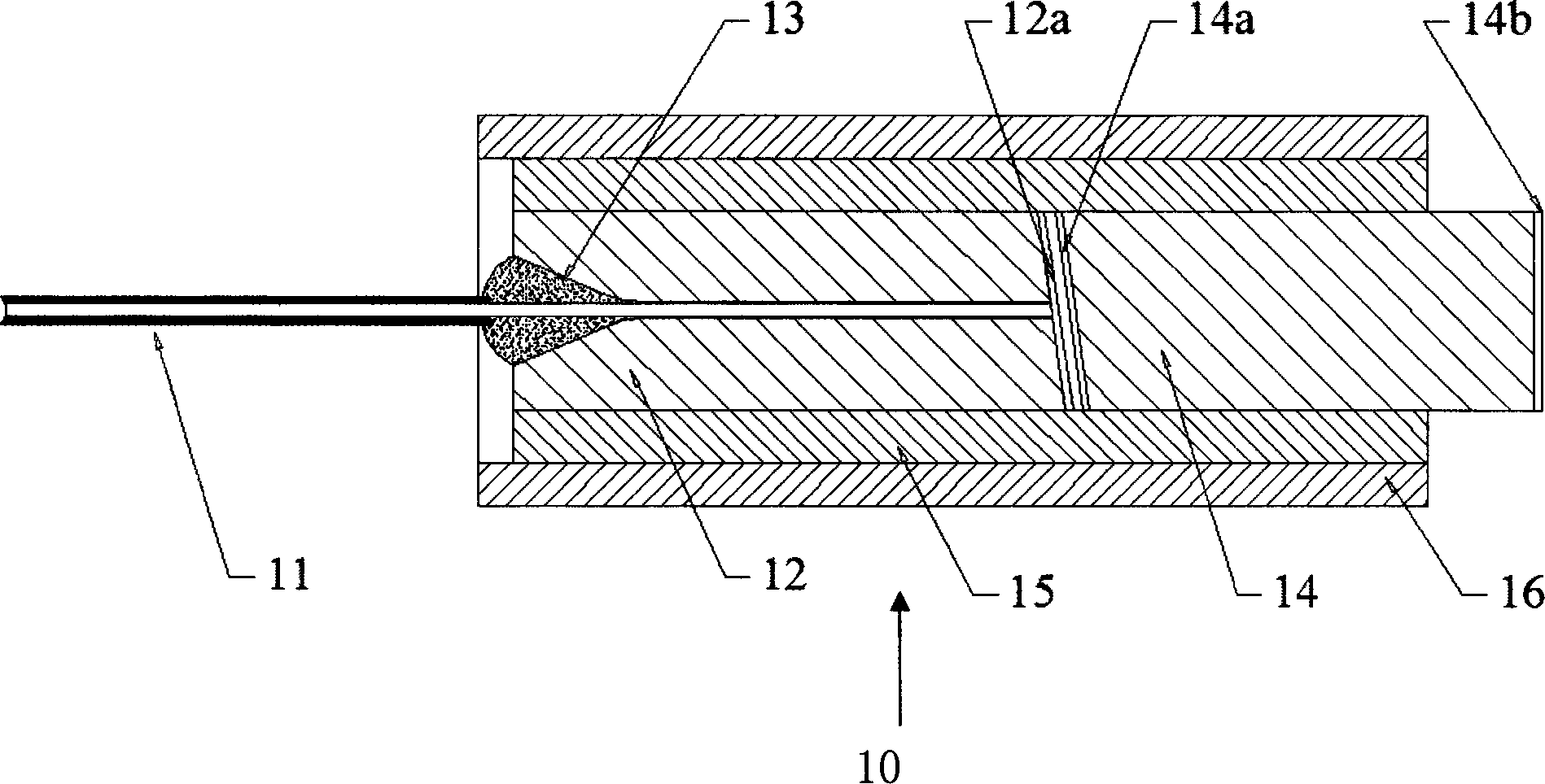
[0023] Example 1: Please refer to the attached figure 1 , which shows a mold for an atypical lens. The manufacture method of described optical fiber collimator, first needs to open mold for special-type lens, makes the mold 100 that can cast and produce special-type lens; This mold 100 has mold cavity, and this mold cavity comprises cylindrical unit 110, conical unit 120 and free The curved surface unit 130 is composed of these three parts to form an injection molding cavity for accommodating the complete entity of the special-shaped lens.

[0024] The cylindrical unit 110 includes a first plane 111 , a second plane 113 and a curved surface 112 , and the curved surface 113 connects the first plane 111 and the second plane 112 . And this cone unit 120 comprises maximum diameter plane 123, minimum diameter plane 121 and the conical surface 122 that connects maximum diameter plane 123 and minimum diameter plane 121, and maximum diameter plane 123 and minimum diameter plane 121 a...

Embodiment 2

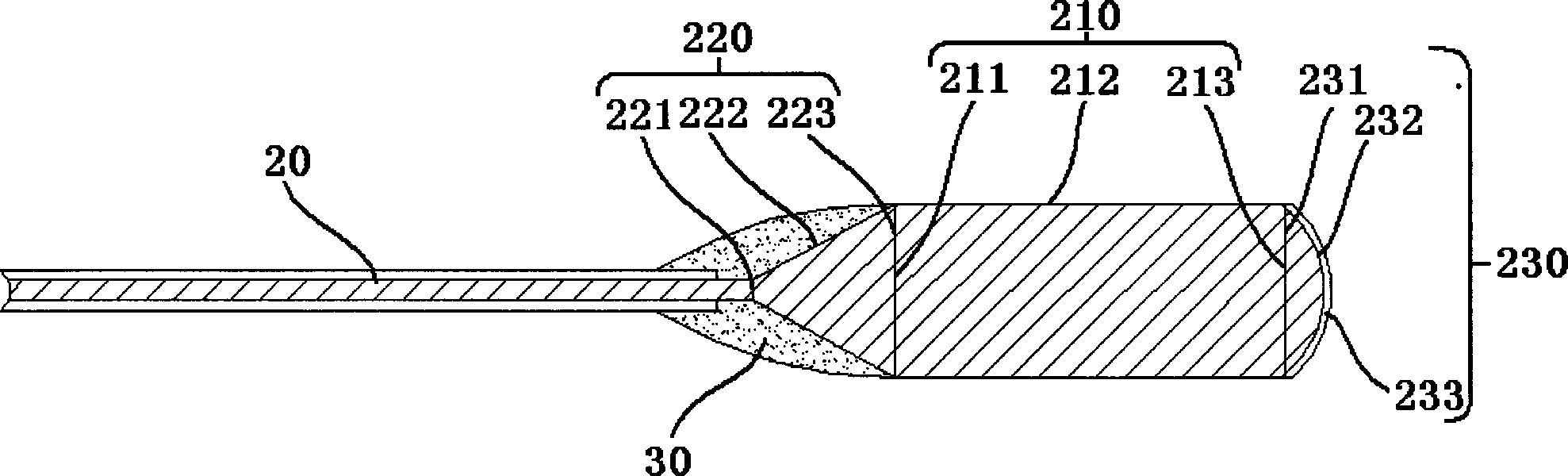
[0034] In this embodiment, the atypical lens 300 is different from that in Embodiment 1. The difference is that the atypical lens 300 includes a conical portion 320, a cylindrical portion 310, and a free-form surface portion 330, and the cylindrical portion 210 includes a first plane 311, a second plane 313 and a curved surface 312, the curved surface 312 connects the first plane 311 and the second plane 313; and the conical portion 320 includes a maximum diameter plane 323, a minimum diameter plane 321 and a cone connecting the maximum diameter plane and the minimum diameter plane Face 322, maximum diameter plane 323 and minimum diameter plane 321 are circular planes perpendicular to the central axis of the cone; and the free-form surface part 330 includes a circular plane 331 and a free-form surface 332 formed on the circular plane 331; the cone The maximum diameter of the part 320 is less than the diameter of the cylindrical part 310, the conical part 320 joins the first pla...


PUM


Abstract

The invention relates to an optical fiber collimator. The optical fiber collimator comprises a special lens, an optical fiber and optical structural adhesive, wherein the special lens and the optical fiber are in fusion welding connection with each other, and the optical structural adhesive is bonded on the periphery of a welding point of the optical fiber and the special lens; and the optical fiber and the special lens are made of the same material. The junction between the optical fiber and the lens is unnecessary to polish and coat; by adopting the compression molding technology, the mass production of the lens can be realized; the overall size can be miniaturized to be consistent with the diameter of the optical fiber, so that the optical fiber collimator can be maximally miniaturized and integrated; and fewer components are needed, the optical fiber and the lens can be welded simply by centering, the complicated adjustment of a light path is not needed, the assembling process is simpler, and the cost is lower. The optical fiber and the lens are made of the same material, so that the light passes through the fewest medium layers, and the return loss can be minimized.

Description

【Technical field】 [0001] The invention relates to the field of optical fiber communication network and optical fiber communication equipment, in particular to an optical fiber collimator, which collimates the light emitted by the optical fiber. 【Background technique】 [0002] An optical communication network is composed of multiple optical devices, and the accuracy and coupling efficiency between optical fibers and other optical devices affect the performance of the optical communication network. Therefore, fiber collimators are needed to improve the coupling efficiency between optical fibers or optical fibers and devices, and reduce insertion loss. Optical fiber collimators are one of the basic devices for constructing optical communication systems and networks. With the continuous advancement of optical fiber communication technology, the manufacture of optical fiber collimators is developing in the direction of reducing the complexity of the structure, reducing the volume...

Claims


Application Information

Patent Timeline
Patent Type & Authority Applications(China)
IPC IPC(8): G02B6/32G02B6/26G02B6/255G02B1/10
Inventor 黄燕平李立周小平张怀忠
Owner 深圳市天阳谷科技发展有限公司
Why Eureka
Try Eureka