
Grid-controlled electron gun digital power supply for medical electron linear accelerator

A linear accelerator, grid-controlled electron gun technology, applied in electrical components, irreversible AC power input into DC power output, output power conversion devices, etc., can solve interference, shorten the life of the electron gun, insufficient emission or overcurrent, etc. It can reduce the interference of high voltage output stability, ensure long-term working stability, and achieve the effect of stable emission beam.

Active Publication Date: 2013-08-14
江苏海明医疗器械有限公司 +1
View PDF3 Cites 21 Cited by
  • Summary
  • Abstract
  • Description
  • Claims
  • Application Information

AI Technical Summary

Problems solved by technology

[0005] (1) It is difficult to control and adjust the emission beam of the electron gun alone, and the actual emission is insufficient or over-current, which seriously affects the working state of the electron gun and shortens the service life of the electron gun;
[0006] (2) The strong pulse current of the magnetron oscillator interferes with the control circuit of the electron gun through coupling, making the emission beam of the electron linear accelerator not stable enough;
[0007] (3) The amplitude of the generated high voltage cannot be adjusted independently, and cannot provide the best working voltage required by the electron gun in various working modes

Method used


Image

  • Grid-controlled electron gun digital power supply for medical electron linear accelerator
  • Grid-controlled electron gun digital power supply for medical electron linear accelerator
  • Grid-controlled electron gun digital power supply for medical electron linear accelerator

Examples


Embodiment Construction

[0047] The present invention will be described in detail below with reference to the drawings and embodiments.

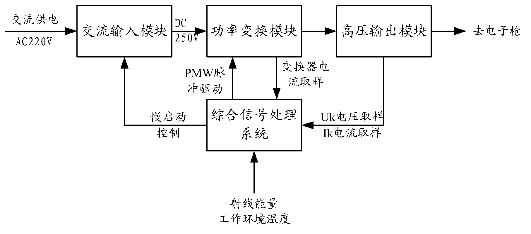
[0048] Such as figure 1 As shown, the grid-controlled electronic gun digital high-frequency high-voltage power supply for medical electron linear accelerators of the present invention includes an AC input module, a power conversion module, a high-voltage output module, and an integrated signal processing system.

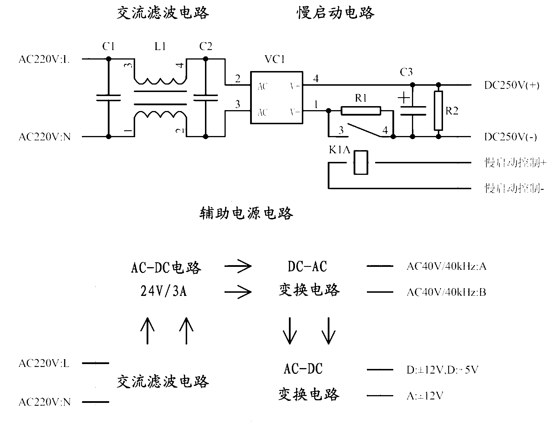
[0049] figure 2 Is the functional block diagram of the AC input module, such as figure 2 As shown, the AC input module includes an AC filter circuit, a slow start circuit, and an auxiliary power circuit.

[0050] The AC input module uses EMI filters to achieve electromagnetic compatibility. The EMI filter consists of capacitors C1, C2 and inductor L1. The slow start circuit is composed of rectifier bridge V1, current limiting resistor R1, energy storage capacitor C3, relay K1A and resistor R2. The input of the rectifier bridge V1 is connected to the output of...


PUM


Abstract

The invention discloses a grid-controlled electron gun digital power supply for a medical electron linear accelerator. The grid-controlled electron gun digital power supply comprises an alternating current input module, a power conversion module, a high voltage output module and a comprehensive signal processing system, wherein the alternating current input module is used for filtering and rectifying input alternating current power, performing slow start control on the input alternating current power and providing low voltage auxiliary power for the entire power supply; direct current voltage generated by the alternating current input module is converted into high frequency pulse in the power conversion module; the high voltage output module is used for boosting, rectifying and filtering the high frequency pulse and outputting direct current high voltage Uk; digital loop control is designed in the comprehensive signal processing system; and PWM (Pulse Width Modulation) control is compensated through sampling ray energy and power supplyvoltage fluctuationand real-time dynamic response is made in combination with a PID (Proportion Integration Differentiation) control algorithm, so that the influence of fluctuation in the power grid on an emission beam of the electron gun is eliminated. The sampled data is corrected according to the ambient temperature, so that the interference of ambient temperature variation in high voltage output stability is reduced, and the stability for long-term work of the electron gun is guaranteed.

Description

Technical field [0001] The invention relates to the technical field of grid-controlled electron gun power supply design, in particular to a grid-controlled electron gun digital high-frequency high-voltage power supply for medical electronic linear accelerators. Background technique [0002] In the application of medium and high-energy medical electron linear accelerators, the grid-controlled electron gun that can emit beams stably is an important part of the system. [0003] In order to ensure the normal operation of the electron gun, it is necessary to ensure that the voltage provided for each level of the electron gun has a high degree of stability, and the cathode high-voltage power supply circuit is particularly critical. It is necessary to design a high-frequency and high-voltage power supply circuit for an electron gun, which generates a stable and controllable DC high-voltage power supply, so as to ensure the stable output and precise adjustment of the beam emitted by the el...

Claims


Application Information

Patent Timeline
IPC IPC(8): H02M7/02H02M1/12H02M1/36H02M3/28
Inventor 黎滨沙亮张彦毕磊王小军吴建兴王春波
Owner 江苏海明医疗器械有限公司
Learn More