Low-power consumption oscillating circuit

An oscillating circuit and low power consumption technology, which can be applied to the field of power consumption requirements

Active Publication Date: 2013-08-14
杭州中科微电子有限公司
View PDF11 Cites 23 Cited by
  • Summary
  • Abstract
  • Description
  • Claims
  • Application Information

AI Technical Summary

Problems solved by technology

Contents of

Method used


Image

  • Low-power consumption oscillating circuit
  • Low-power consumption oscillating circuit
  • Low-power consumption oscillating circuit

Examples


no. 1 example

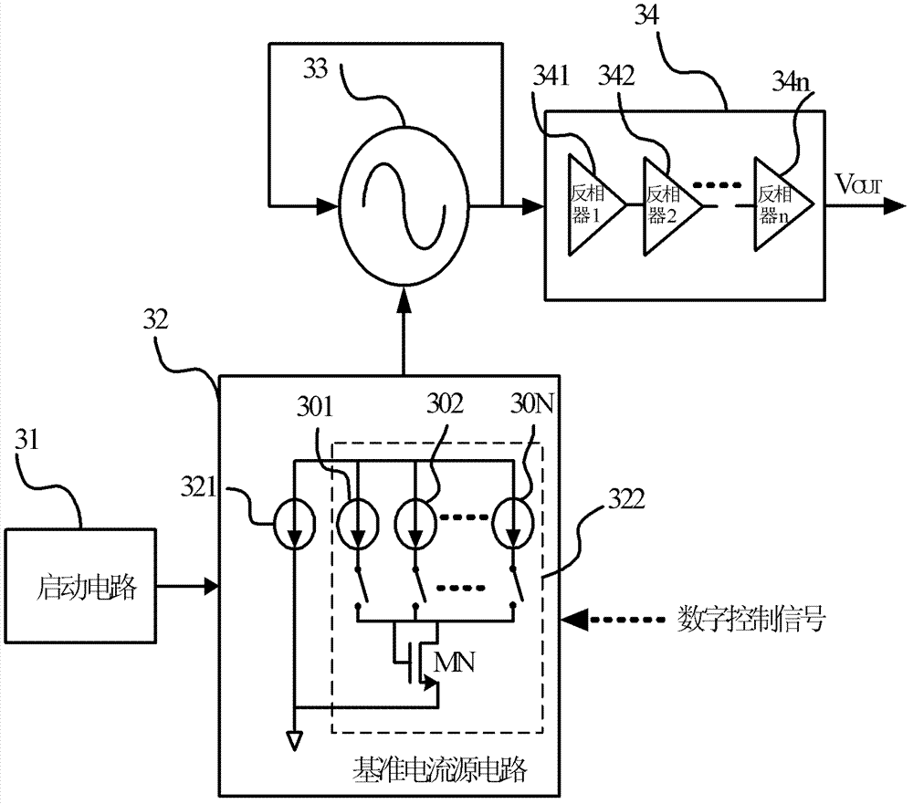
[0074] Figure 3a A block diagram of the low power consumption oscillating circuit of the embodiment of the present invention is given. The low power consumption oscillating circuit is composed of a starting circuit 31 , a reference current source circuit 32 , a controlled oscillating circuit 33 and a driving circuit 34 . The output end of the start-up circuit 31 is connected to the reference current source circuit 32, which is used to change the state of the reference current source circuit 32 from a stable state to a normal working state when powered on. The reference current source circuit 32 includes a constant current source 321 which is a cell reference current source circuit. The reference current source circuit 32 also includes a configurable current source group 322, which includes N mirror current sources 301, 302, ~ 30N, and their currents are all mirrored to the current of the constant current source 321, but the mirror current sources 301, 302, The size of the m...

no. 2 example

[0076] Figure 3bA block diagram of the low power consumption oscillation circuit in which N is 3 according to the embodiment of the present invention is given. The reference current source circuit 32 includes a constant reference current source 321 and a configurable current source 322, the constant tail current source circuit 321 is a reference current source, and the configurable tail current source circuit 322 includes 3 mirror current sources 301 and 302 and 303, they are all mirrored to the mirror current of the constant tail current source 321, but the size of the mirror current is respectively 2, 4, and 6 times of the current of the constant tail current source 321, and also includes the control switch module and the current summary tube MN, the control switch module is controlled by Controlled by an external digital control signal, the current configurable control signal comes from an external digital control signal. The controlled oscillation circuit 33 is supplied ...

no. 3 example

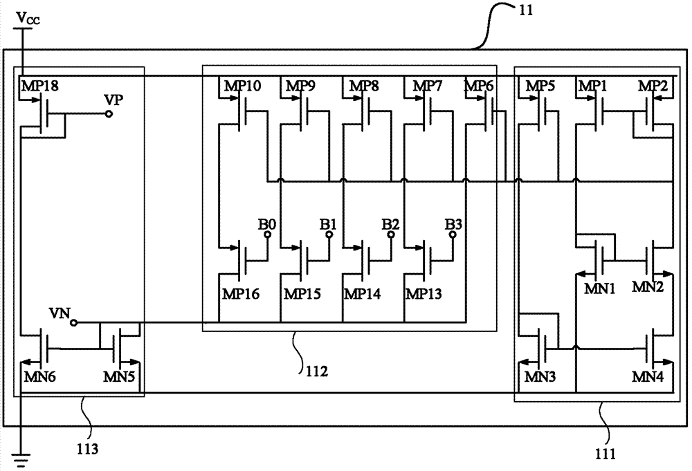
[0078] Figure 4a The schematic diagram of the block diagram of the reference tail current source circuit of the starting circuit and the reference current source circuit of the embodiment of the present invention is given, Figure 4b A schematic diagram of the reference tail current source circuit of the startup circuit and the reference current source circuit of the embodiment of the present invention is given, and the connection relationship between the startup circuit 44 and the reference tail current source circuit is also shown in the figure.

[0079] Such as Figure 4a As shown, the connection relationship between the block diagram of the constant reference current source circuit and the block diagram of the startup circuit and the configurable mirror current source circuit is given. The starting circuit 31 makes the state of the positive current circuit 41 and the negative current circuit 42 of the constant reference current source circuit enter the normal working...


PUM


Abstract

The invention discloses a low-power consumption oscillating circuit. The low-power consumption oscillating circuit comprises a start-up circuit, a controlled oscillation circuit, a reference current source circuit and a drive circuit, wherein the reference current source circuit comprises a constant current source and configurable current source group and a confluence circuit; the controlled oscillation circuit comprises multi-stage identical current-controlled inverter circuits arranged in a cascaded manner; the reference current source circuit generates a reference current which is irrelative to the power supply voltage, the temperature and the process; the size of output currents of the reference current source circuit is configured by external digital control signals; by adjusting the reference current output by the reference current source circuit, the control of oscillation frequency of the controlled oscillation circuit can be realized, while the adjusted reference current can be provided for the drive circuit to serve as the reference voltage; and the frequency generated by the controlled oscillating circuit is output by the drive circuit. The low-power consumption oscillating circuit can be flexibly used in wake-up circuits of various wireless transceiver radio frequency chips, and is particularly suitable for low-power consumption occasions where working voltage is wide in changing range, and the low-power circuit for battery power supply is required..

Description

Background technique [0001] In recent years, with the continuous emergence of new technologies in the field of information technology and the continuous advancement of technology, various applications with limited power consumption need to use low-power wake-up circuits, and the wake-up circuits need to provide clocks that can detect the frequency of the current output signal circuit, and it is required that this clock circuit can cover a wide enough range to ensure that it can be adjusted under the conditions of temperature and process changes and voltage changes. [0002] As we all know, in order to improve the portability and flexibility of the system, short-distance wireless communication systems are powered by batteries. This power supply method requires that most of the wireless communication chips do not work normally, and communicate with the outside through the built-in wake-up circuit. If it is necessary to wake up the entire chip through the internal wake-up circuit...

Claims


Application Information

Patent Timeline
IPC IPC(8): H03L5/00H03B5/04
Inventor 何晓丰钱敏甘业兵马成炎
Owner 杭州中科微电子有限公司
Why Eureka
Try Eureka