Drill with coating at flat base of straight groove, blind hole and single groove

A drill bit and coating technology, applied in drilling/drilling equipment, drill repairing, drilling tool accessories, etc., can solve the problems of mechanical fixed-depth drilling, high drilling force, surface burrs, and short life of the drill bit. Achieve the effect of improving the processing surface burr, strong chip removal ability and improving service life

Active Publication Date: 2013-08-21
SHANGHAI UNIV OF ENG SCI +1
View PDF5 Cites 2 Cited by
  • Summary
  • Abstract
  • Description
  • Claims
  • Application Information

AI Technical Summary

Problems solved by technology

[0002] At present, the processing of blind holes on printed circuit boards has the problems of large drilling force, high temperature, and poor chip removal during mechanical fixed-depth drilling. The use of twist drills has the centering of the drill bit. The chisel edge with a very large impact on the drilling force, especially when the hole depth is greater than the hole diameter, will cause burrs on the machined surface and uneven bottom. The life of the drill bit is short

Method used


Image

  • Drill with coating at flat base of straight groove, blind hole and single groove
  • Drill with coating at flat base of straight groove, blind hole and single groove

Examples


Embodiment

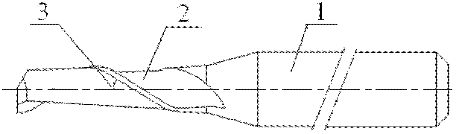
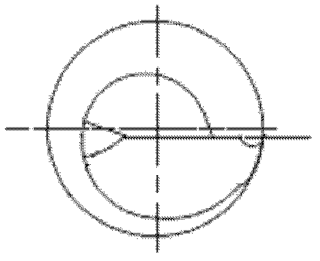
[0022] A straight-fluted, flat-bottomed coated blind hole single-fluted drill bit, the structure of which is as follows Figure 1-2 As shown, the rear part of the drill bit is a clamping part 1 with a diameter of 3.175 mm, and the front part is a cutting part. A chip removal groove 2 is arranged on the flank surface of the cutting part. The angle of the large helix angle is 25-30°, and the angle of the large rotation angle in this embodiment is 28°. The cutting edge of the drill bit passes through the center of the drill bit, and the length of the cutting edge is longer than the radius, so as to solve the problem of uneven hole bottom. The drill bit is made of hard alloy material, and the outside is coated with a layer of titanium aluminum nitride (TiAlN) coating. The diameter of the drill bit can be 0.4-3.0 mm, which is used for different cutting occasions. In this embodiment, the diameter of the drill bit is 1 mm, and the total length of the entire drill bit is 38.10 mm.

...


PUM


Abstract

The invention relates to a drill with a coating at a flat base of a straight groove, a blind hole and a single groove. The back part of the drill is a clamping part; the front part is a cutting part; a chip groove is arranged at the back cutter face of the cutting part; the main body of the cutting part is a big helical angle of 25-30 DEG; the cutting edge of the drill passes through the center of the drill; and a coating layer is plated at the outer part of the drill. Compared with the prior art, the single chip groove is utilized, so that a drill tip having the same angle as the drill rather than a transverse blade exists when the drill drills a printed circuit board; the chip groove is great in size and great in chip containing capability and achieves a good chip removal effect; the length of a blade is greater than a radius, that is to say, a cutting edge goes beyond a core-bit, so that the unevenness problem of a hole bottom is solved; in addition, the TiAlN coating with the heat transfer coefficient much lower than that of a drill base body and a work-piece material is additionally arranged. Therefore, the heat energy absorbed by the drill is relatively low, a relatively high drilling temperature can be borne, and the service life of the cutter is prolonged by up to 40%.

Description

technical field [0001] The invention relates to a drill bit, in particular to a straight groove flat bottom coating blind hole single groove drill bit. Background technique [0002] At present, the processing of blind holes on printed circuit boards has the problems of large drilling force, high temperature, and poor chip removal during mechanical fixed-depth drilling. The use of twist drills has the centering of the drill bit. And the chisel edge with a very large impact on the drilling force, especially when the hole depth is greater than the hole diameter, will cause burrs on the machined surface and uneven bottom, and the life of the drill bit will be short. Therefore, the design of the drill bit must be designed with a reasonable shape and coating to reduce the drilling force and friction and wear. Now a straight-groove flat-bottom coated blind hole single-groove drill is used to solve the problems of burrs in the hole and uneven bottom of the hole; the diameter can be ...

Claims


Application Information

Patent Timeline
Patent Type & Authority Applications(China)
IPC IPC(8): B23B51/00
Inventor 黄立新蓝兴杰
Owner SHANGHAI UNIV OF ENG SCI
Why Eureka
Try Eureka