Manufacturing method for abrasive grain tool
An abrasive particle and tool technology is applied in the field of abrasive particle tool preparation to achieve the effect of reducing manufacturing cost, ensuring stability and ensuring continuity
- Summary
- Abstract
- Description
- Claims
- Application Information
AI Technical Summary
Problems solved by technology
Method used
Image


Examples
example 1
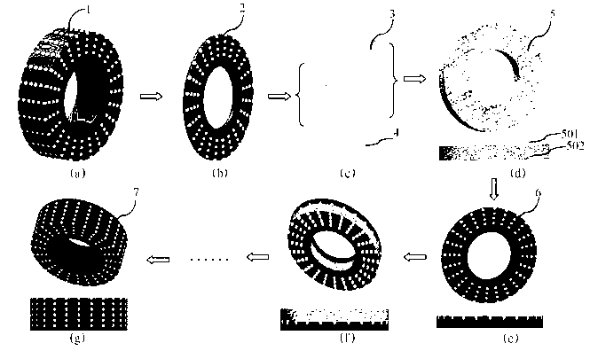
[0036]For ordinary flat grinding wheels, ProE software is used for physical construction, and the abrasive grains are arranged in concentric circles. Through layering, the mutual information of the binder and abrasive grains of each layer is obtained; using nickel-based alloy powder, the powder is prepared according to the The design is placed in a ring shape, the thickness of the alloy powder layer is 1mm, and 40 / 50 mesh diamond abrasive grains are placed above it, and the sintering of the bonding agent is completed by laser, so that the bonding agent is solidified point by point, and the abrasive particles are held; On top of it, alloy powder layer and abrasive grain layer are placed sequentially according to the entity structure information, and solidified again until the whole grinding wheel is completed.
example 2
[0038] This example is similar to Example 1, but the designed powder layer is two different alloy powders, wherein the thickness of the nickel-based alloy powder layer is 0.6mm, and a 40 / 50 mesh diamond abrasive grain is placed above it, and the laser is used to complete the alignment. The sintering of the bonding agent solidifies the bonding agent point by point and holds the abrasive grains; a copper-based alloy powder layer with a thickness of 0.5mm is placed above the bonding layer, and laser sintering is used to complete the curing of the copper-based alloy layer, thereby obtaining a composite Sintered layer: on the composite sintered layer, rotate the nickel-based alloy powder layer and the diamond abrasive grain layer, repeat the above steps until the whole grinding wheel is completed, and obtain a grinding wheel with a layered structure in the axial direction.
example 3
[0040] For ordinary butterfly grinding wheels, use AutoCAD software for three-dimensional structure, and set the abrasive grains to be evenly spaced, and obtain the information of the binder and abrasive grains through layered processing; The resin of mm is coated on the substrate according to the pre-designed shape, and 70 / 80 mesh CBN abrasive grains are placed on it; the resin is cured by ultraviolet rays to obtain a cured layer; on the cured layer, light curing is placed again according to the entity structure information The resin, as well as the grit layer, are cured again until the complete wheel is complete.
PUM
| Property | Measurement | Unit |
|---|---|---|
| Thickness | aaaaa | aaaaa |
| Thickness | aaaaa | aaaaa |
| Thickness | aaaaa | aaaaa |
Abstract
Description
Claims
Application Information
 - Generate Ideas
- Intellectual Property
- Life Sciences
- Materials
- Tech Scout
- Unparalleled Data Quality
- Higher Quality Content
- 60% Fewer Hallucinations
Browse by: Latest US Patents, China's latest patents, Technical Efficacy Thesaurus, Application Domain, Technology Topic, Popular Technical Reports.
© 2025 PatSnap. All rights reserved.Legal|Privacy policy|Modern Slavery Act Transparency Statement|Sitemap|About US| Contact US: help@patsnap.com