
Switch reluctance motor system

A technology of switched reluctance motor and motor current, applied in the direction of torque ripple control, etc., can solve the problems of high cost, fuzzy control of DSP angle, complex system, etc., and achieve the effect of improving performance and improving vibration and noise

Inactive Publication Date: 2013-08-28
WENLING DONGYANG GEAR SPEED CHANGE MOTOR CO LTD
View PDF5 Cites 8 Cited by
  • Summary
  • Abstract
  • Description
  • Claims
  • Application Information

AI Technical Summary

Problems solved by technology

In order to adapt to the good performance of switched reluctance motors in high-speed operation, at present, DSP angle fuzzy control is mostly used at home and abroad, the system is complicated and the cost is high

Method used

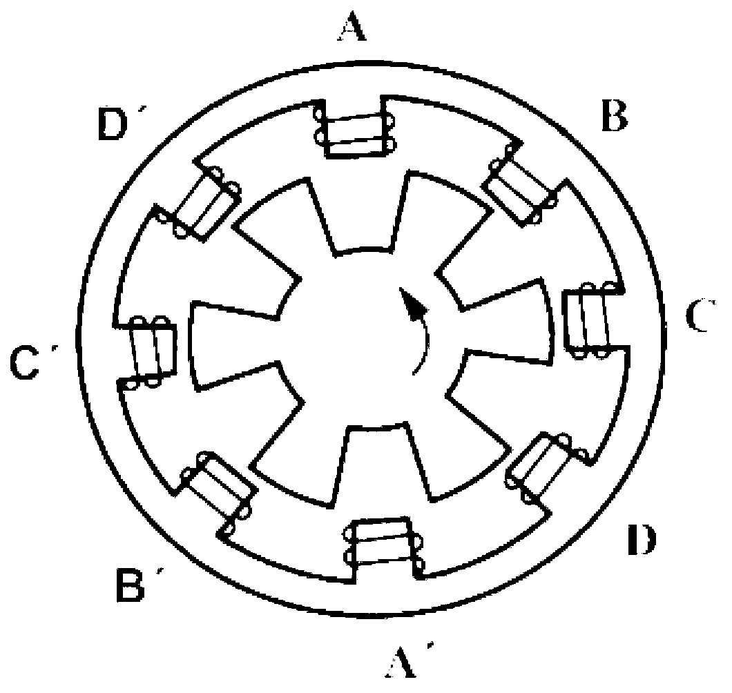
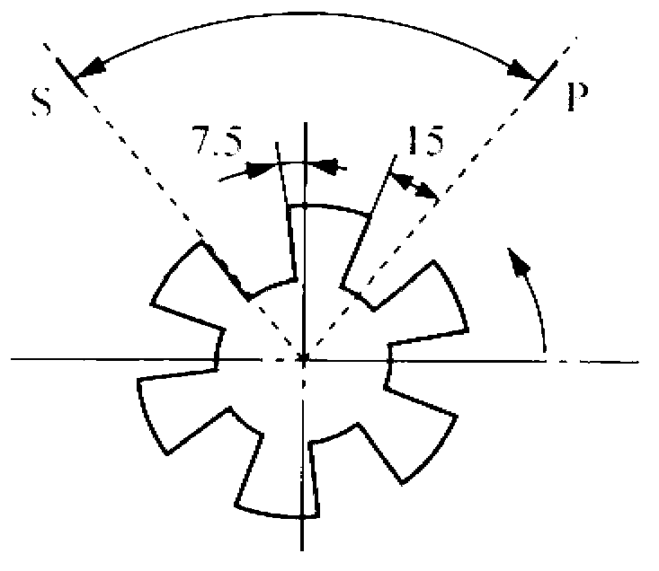

Image

  • Switch reluctance motor system
  • Switch reluctance motor system
  • Switch reluctance motor system

Examples


Embodiment Construction

[0025] In order to make the object, technical solution and advantages of the present invention clearer, the present invention will be further described in detail below in conjunction with the accompanying drawings and embodiments. It should be understood that the specific embodiments described here are only used to explain the present invention, not to limit the present invention.

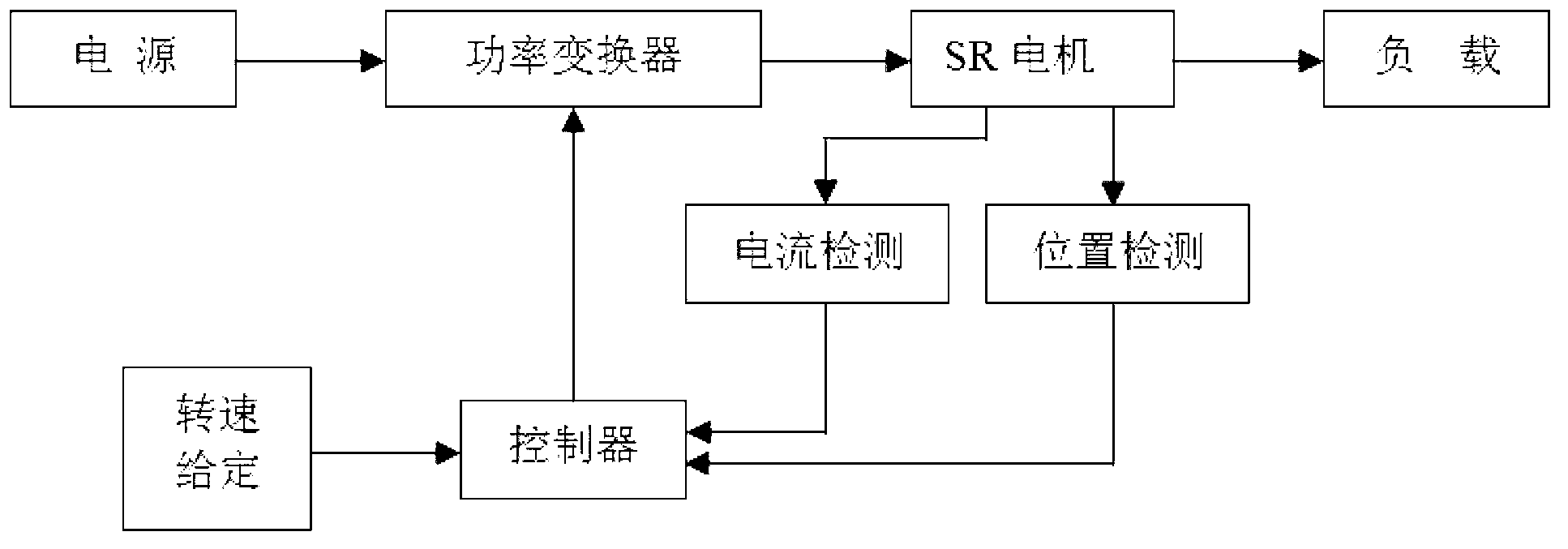
[0026] A switched reluctance motor system of the present invention adopts all hardware circuits to form a digital angle control link to realize the forward translation of the conduction angle and the cut-off angle, and when the motor speed reaches the set speed, the angle control is started to conduct in advance Angle and turn-off angle, that is, to translate the turn-on and turn-off waveforms forward, this control method can well improve the motor torque and vibration noise of the motor.

[0027] Such as figure 1 As shown, the switched reluctance motor system of the present invention includes a p...


PUM


Abstract

The invention discloses a switch reluctance motor system. The switch reluctance motor system comprises a power supply, a power transformer which is connected with the power supply, a switch reluctance (SR) motor which is connected with a power variator, a load which is connected with the SR motor, an SR motor current detecting part, an SR motor position detecting part, a controller which is respectively connected with the SR motor current detecting part and the SR motor position detecting part and a phase compensation circuit. The switch reluctance motor system completely adopts a hardware circuit to form a digital angular control link, so that a conduction angle and a turn-off angle are translated forwards, the angle control is started when the rotation speed of the motor reaches a set rotation speed, the angle is conducted and turned off in advance, namely a conduction and turn-off waveform is translated forwards, thus the control method can well improve the motor torque and the motor vibration noise, and the operation performance of the switch reluctance motor at a high speed can be improved.

Description

technical field [0001] The invention relates to a switched reluctance motor system. Background technique [0002] Switched reluctance motor, as a new type of speed-regulating drive system, is more and more recognized and applied by people because of its simple structure, low cost, high efficiency, excellent speed regulation performance and flexible controllability. At present, it has been successfully applied in many fields such as electric vehicle drive system, household appliances, industrial application, servo system, high-speed drive, aerospace, etc., and has become AC motor speed control system, DC motor speed control system and brushless DC motor speed control A strong contender for the system. [0003] In recent years, with the rapid development of power electronics technology, digital signal processing technology and control technology, and with the continuous maturity of intelligent technology and the emergence of high-speed, high-efficiency and low-cost digital si...

Claims


Application Information

Patent Timeline
Patent Type & Authority Applications(China)
IPC IPC(8): H02P6/10
Inventor 徐学先
Owner WENLING DONGYANG GEAR SPEED CHANGE MOTOR CO LTD
Learn More