
Oxygen-hydrogen co-production device and method based on chemical chain reaction

A technology of chemical chain and oxygen, applied in the field of chemical chain, can solve the problems of high energy consumption, high energy consumption of hydrogen production, unsuitable for industrial production, etc., and achieve the effects of low energy consumption, reduced production cost and simple equipment

Active Publication Date: 2013-09-04
NORTHEASTERN UNIV
View PDF2 Cites 24 Cited by
  • Summary
  • Abstract
  • Description
  • Claims
  • Application Information

AI Technical Summary

Problems solved by technology

The current chemical chain oxygen generator reactor is divided into a deoxidation reactor and an oxidation reactor. The oxygen carrier releases oxygen in the deoxidation reactor, and the released oxygen is carried out by the carrier gas introduced from the lower part. The device reacts with the incoming air and absorbs the oxygen in the air to be regenerated; hydrogen is the lightest gas known in the world. It is not only a high-quality fuel, but also an important It is considered to be one of the important clean energy sources in the future. According to the source of raw materials, existing hydrogen production technologies can be divided into hydrogen production from fossil fuels and hydrogen production from renewable resources. The former is currently the dominant method of hydrogen production, accounting for about 95% of the market share, but the energy consumption of hydrogen production in this way is very large
[0004] At present, the method of producing hydrogen and oxygen at the same time is mainly based on electrolysis of water. This method consumes a lot of energy and is not suitable for large-scale industrial production.

Method used


Image

  • Oxygen-hydrogen co-production device and method based on chemical chain reaction
  • Oxygen-hydrogen co-production device and method based on chemical chain reaction
  • Oxygen-hydrogen co-production device and method based on chemical chain reaction

Examples


Embodiment 1

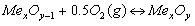
[0033] (1) Add the copper-based oxygen carrier particles into the oxygen-generating fluidized bed from the feeding port of the oxygen-generating fluidized bed, control the temperature of the oxygen-generating fluidized bed in the oxygen-generating fluidized bed to 1100°C, and Deoxygenation reaction and release of oxygen;

[0034] Open the flow control device of the carrier gas inlet of the oxygen-producing fluidized bed, and pass in the pure oxygen carrier gas. The ratio of the carrier gas flow rate to the oxygen flow rate released by the reaction is controlled at 5:1. The final oxygen carrier particles also enter the oxygen generation cyclone separator, and the gas-solid separation is carried out in the oxygen generation cyclone separator. The carrier gas and oxygen enter the oxygen storage cabinet through the upper exhaust port of the oxygen generation cyclone separator. Oxygen particles enter the feed port of the hydrogen production fluidized bed through the lower part of t...

Embodiment 2

[0045] (1) Add the cobalt-based oxygen carrier particles into the oxygen-generating fluidized bed from the feeding port of the oxygen-generating fluidized bed, control the temperature of the oxygen-generating reactor in the oxygen-generating fluidized bed to 800°C, and Deoxygenation reaction and release of oxygen;

[0046] Open the flow control device of the carrier gas inlet of the oxygen-producing fluidized bed, and pass in the carbon dioxide carrier gas. The ratio of the carrier gas flow rate to the oxygen flow rate released by the reaction is controlled at 3:1. The oxygen is brought into the oxygen-producing cyclone separator by the carrier gas. After deoxygenation The oxygen carrier particles also enter the oxygen generation cyclone separator, and the gas-solid separation is carried out in the oxygen generation cyclone separator. The carrier gas and oxygen enter the oxygen storage cabinet through the upper exhaust port of the oxygen generation cyclone separator. The solid...

Embodiment 3

[0052] (1) Add manganese-based oxygen carrier particles into the oxygen-generating fluidized bed from the feed / feed port of the oxygen-generating fluidized bed, control the temperature of the oxygen-generating fluidized bed in the oxygen-generating fluidized bed to 500°C, and Deoxygenation reaction and release of oxygen;

[0053] Open the flow control device of the carrier gas inlet of the oxygen production fluidized bed, and introduce industrial flue gas rich in carbon dioxide as the carrier gas. The ratio of the flow rate of the carrier gas to the oxygen flow rate released by the reaction is controlled at 1:1, and the oxygen is brought into the oxygen production by the carrier gas. In the cyclone separator, the deoxygenated oxygen carrier particles also enter the oxygen generation cyclone separator, and the gas-solid separation is carried out in the oxygen generation cyclone separator, and the carrier gas and oxygen enter the oxygen storage cabinet through the upper exhaust p...


PUM

PropertyMeasurementUnit
Diameteraaaaaaaaaa
Mechanical strengthaaaaaaaaaa

Abstract

The invention belongs to the technical field of chemical chains, and in particular relates to an oxygen-hydrogen co-production device and method based on chemical chain reaction. According to the oxygen-hydrogen co-production device based on the chemical chain reaction, an oxygen production fluidized bed is connected with an oxygen production cyclone separator which is connected with a feed port of a hydrogen production fluidized bed, a hydrogen production fluidized bed gas outlet is formed in the upper part of the hydrogen production fluidized bed and is connected with a hydrogen production cyclone separator, and the lower part of the hydrogen production cyclone separator is connected with a fixed bed feed port in the top of a fixed bed. An oxygen carrier is subjected to deoxidization reaction in the oxygen production fluidized bed to generate oxygen, the deoxidized oxygen carrier particle enters into the hydrogen production fluidized bed to react with water vapor to produce hydrogen, the reacted oxygen carrier particle enters into the fixed bed to react with the oxygen to be regenerated, and the regenerated oxygen carrier particle is returned to the oxygen production fluidized bed to be recycled. The device provided by the invention is simple, and the method can be carried out at normal pressure; and compared with a traditional oxygen production method and a traditional hydrogen production method, energy consumption is less and production cost is reduced.

Description

technical field [0001] The invention belongs to the technical field of chemical chain reaction, and in particular relates to an oxygen-hydrogen cogeneration device and method based on chemical chain reaction. Background technique [0002] In 1983, German scholar Richter proposed the chemical looping combustion (CLC) technology. The device is mainly composed of a fuel reactor and an air reactor. The separation of air and fuel in the combustion process is achieved by relying on the circulation of oxygen carriers between the two reactors. The solubility of carbon dioxide in the gas is greatly increased, which facilitates the capture of carbon dioxide. With the deepening of people's understanding of chemical chain technology, some other chemical chain technologies have emerged, such as: oxygen decoupling chemical chain combustion (CLOU) technology, chemical chain reforming (CLR) technology, chemical chain hydrogen production (TRCL) technology, Chemical looping steam reforming h...

Claims


Application Information

Patent Timeline
IPC IPC(8): C01B13/02C01B3/06
CPCY02E60/36
Inventor 于庆波王坤白敬晨秦勤
Owner NORTHEASTERN UNIV
Features
  • Generate Ideas
  • Intellectual Property
  • Life Sciences
  • Materials
  • Tech Scout
  • Unparalleled Data Quality
  • Higher Quality Content
  • 60% Fewer Hallucinations
Learn More