Cavity ring-down fiber grating sensing demodulating device based on calibrated fiber grating

A technology for calibrating optical fibers and fiber gratings, applied in light demodulation, using optical devices to transmit sensing components, optics, etc., can solve problems such as system performance limited by environmental factors, limited light source wavelength, drift, etc.

Active Publication Date: 2013-09-04
NANCHANG HANGKONG UNIVERSITY
View PDF3 Cites 16 Cited by
  • Summary
  • Abstract
  • Description
  • Claims
  • Application Information

AI Technical Summary

Problems solved by technology

However, the cavity ring-down fiber grating demodulation technology that has been proposed so far only uses the sensing fiber grating
The disadvantage of such systems is that system performance is limited not only by environmental factors such as temperature or strain, but also by light source wavelength drift
Environmental factors cause changes in the refractive index and cavity length of the optical fiber ring cavity, resulting in changes in the ring-down time constant of the cavity, resulting in demodulation errors in the fiber grating sensing system, and ultimately affecting the measurement accuracy of external parameters
Light with different wavelengths has different transmittance after passing through the fiber grating. Therefore, the wavelength drift of the light source will also cause the change of the ring-down time constant of the cavity, which will cause the demodulation error of the fiber grating sensing system, and finally affect the measurement accuracy of external parameters.

Method used


Image

  • Cavity ring-down fiber grating sensing demodulating device based on calibrated fiber grating
  • Cavity ring-down fiber grating sensing demodulating device based on calibrated fiber grating

Examples


Embodiment Construction

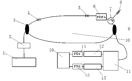
[0014] Such as figure 1 As shown, the present invention is realized in this way, it comprises dual-wavelength tunable narrow-linewidth laser 1, optical switch 2, optical coupler I 3, calibration fiber grating 4, sensing fiber grating 5, erbium-doped fiber amplifier 6, light ring shaper 7, denoising fiber grating 8, optical coupler II9, fiber ring cavity 10, optical coupler III11, optical filter I12, optical filter II13, photodetector I14, photodetector II15 and signal processor 16, Its structural feature is that an optical switch 2 is connected between the dual-wavelength tunable narrow-linewidth laser 1 and the optical coupler I3, and the optical fiber ring cavity 10 is sequentially connected with the optical coupler I3, the calibration fiber Bragg grating 4, and the sensing fiber Bragg grating 5 in a clockwise direction. , erbium-doped fiber amplifier 6, optical circulator 7 and optical coupler Ⅱ 9, optical circulator 7 is also connected with denoising fiber grating 8, optic...


PUM


Abstract

A cavity ring-down fiber grating sensing demodulating device based on a calibrated fiber grating is characterized in that an optical switch is connected between a dual-wavelength tunable narrow linewidth laser and an optical coupler I. An optical fiber annular cavity is sequentially connected with the optical coupler I, the calibrated fiber grating, a sensing fiber grating, an erbium-doped optical fiber amplifier, an optical circulator and an optical coupler II in the clockwise direction. The optical circulator is further connected with a denoising fiber grating. An optical coupler III is connected with the optical coupler II. An optical fiber I and an optical fiber II are both connected with the optical coupler III. A photoelectric detector I is connected between the optical fiber I and a signal processor. A photoelectric detector II is connected between the optical fiber II and the signal processor. According to the cavity ring-down fiber grating sensing demodulating device based on the calibrated fiber grating, temperature and strain of the calibrated fiber grating are accurately controlled, cavity ring-down time constant difference of sensing wavelength and calibrating wavelength is measured so that the temperature or the strain of the sensing fiber grating can be obtained, and influence on system performance by light source wavelength shift and environment factors is eliminated.

Description

technical field [0001] The invention relates to a cavity ring-down optical fiber grating sensor demodulation device based on a calibrating optical fiber grating. Background technique [0002] Cavity ring-down technology is mainly used for testing in the field of spectroscopy, and has trace detection capabilities. In recent years, fiber grating stress sensing based on cavity ring down has been proposed. However, the cavity ring-down fiber grating demodulation technology that has been proposed so far only uses the sensing fiber grating. A disadvantage of such systems is that system performance is limited not only by environmental factors such as temperature or strain, but also by light source wavelength drift. Environmental factors cause changes in the refractive index and cavity length of the fiber ring cavity, resulting in changes in the ring-down time constant of the cavity, causing demodulation errors in the fiber grating sensing system, and ultimately affecting the meas...

Claims


Application Information

Patent Timeline
Patent Type & Authority Applications(China)
IPC IPC(8): G01D5/353G02F2/00
Inventor 万生鹏何兴道
Owner NANCHANG HANGKONG UNIVERSITY
Why Eureka
Try Eureka