High-speed optical receiver module of integrated limiting amplifier and preparation method for high-speed optical receiver module

A technology of limiting amplifier and optical receiving component, applied in the field of optical communication, can solve the problems of high power consumption, low cost, low power consumption limitation of small package, unfavorable optical module debugging, etc., to save design space, reduce cost, The effect of reducing power consumption

Active Publication Date: 2013-09-04
WUHAN TELECOMM DEVICES
View PDF4 Cites 6 Cited by
  • Summary
  • Abstract
  • Description
  • Claims
  • Application Information

AI Technical Summary

Problems solved by technology

[0004] At present, in the commercial optical receiving components, the PD and the preamplifier are still mixed and packaged in a package, and the limiting amplifier used in conjunction with it is placed on the back-end PCB module; this design makes low cost, small The demand for packaging and low power consumption is limited, which has become a bottleneck for the development of the communication industry
Conventional optical receiving components, especially high-speed optical receiving components, do not include limiting amplifiers. The limiting amplifiers are still set on the PCB module, which consumes a lot of power, which is not conducive to the debugging of optical modules; the back-end module is added Difficulty in system design, unable to realize small package and low-cost module design, thus unable to provide higher access density, which will eventually lead to failure to increase user access capacity

Method used


Image

  • High-speed optical receiver module of integrated limiting amplifier and preparation method for high-speed optical receiver module
  • High-speed optical receiver module of integrated limiting amplifier and preparation method for high-speed optical receiver module

Examples


Embodiment Construction

[0018] The present invention will be further described below in conjunction with the accompanying drawings and specific embodiments, so that those skilled in the art can better understand the present invention and implement it, but the examples given are not intended to limit the present invention.

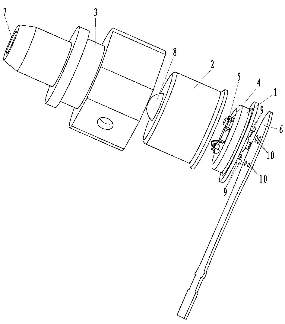
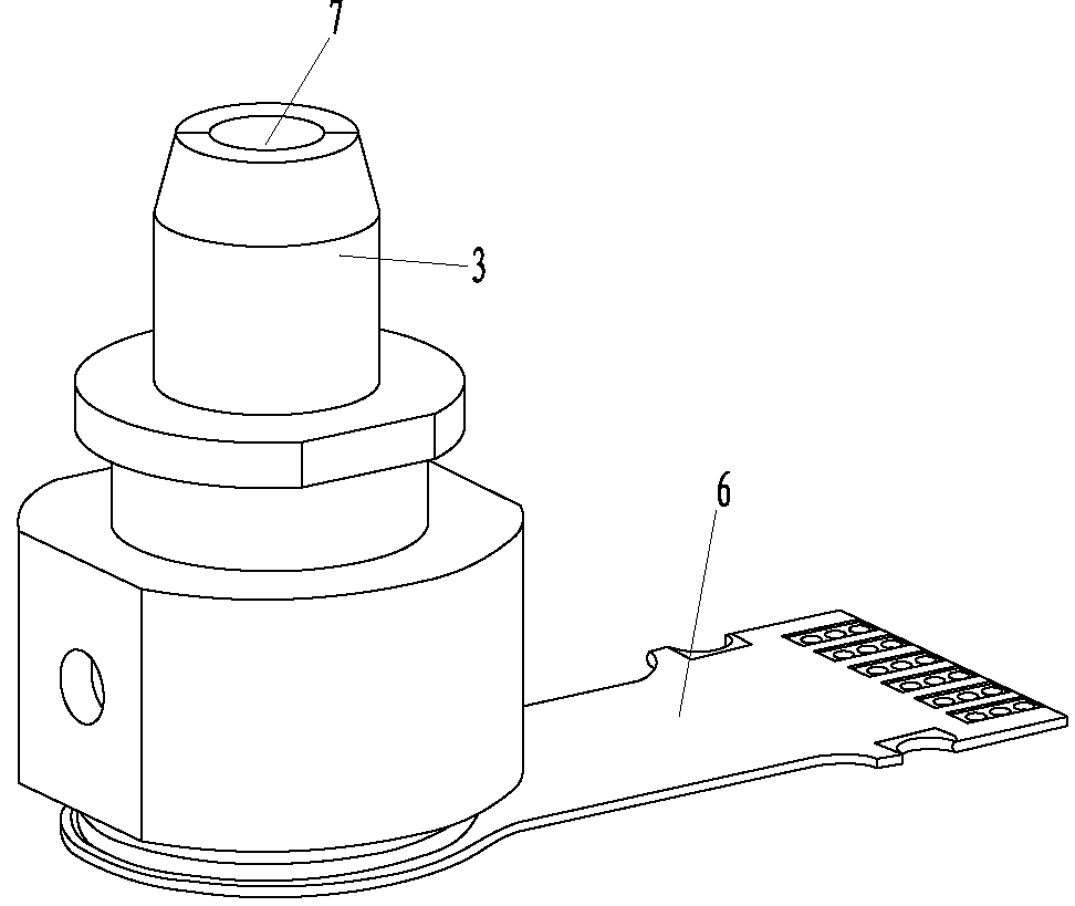
[0019] Such as figure 1 and figure 2 As shown, the high-speed light-receiving component of the integrated limiting amplifier of the present invention includes a tube base 1, a tube cap 2, a plastic adapter 3, a photoelectric receiver 4, a monolithic integrated high-speed limiting amplifier chip 5 and a flexible circuit board 6. The tube cap 2 is sealed and installed on the tube base 1 , and the adapter 3 is fixed on the periphery of the tube cap 2 . The axis of the through hole 7 on the adapter 3 coincides with the axis of the convex lens 8 on the cap 2 . Such as figure 1 As shown, the photoelectric receiver 4 and the single-chip integrated high-speed limiting amplifier chip 5...


PUM


Abstract

The invention discloses a high-speed optical receiver module of an integrated limiting amplifier and a preparation method for the high-speed optical receiver module. The optical receiver module is formed by connecting a tube socket, a tube cap, an adapter, a photoelectric receiver, a monolithic integration high-speed limiting amplifier chip and a flexible printed circuit board, wherein the photoelectric receiver, the monolithic integration high-speed limiting amplifier chip and the flexible printed circuit board are connected with each other. The preparation method for the high-speed optical receiver module comprises the following steps: firstly mounting the photoelectric receiver and the monolithic integration high-speed limiting amplifier chip onto the tube socket; then, welding the photoelectric receiver and the input end of the monolithic integration high-speed limiting amplifier chip together by using a gold wire bonder, and meanwhile, welding a bonding pad of the monolithic integration high-speed limiting amplifier chip and pins of the tube socket together; then, sealing the tube cap by adopting a cap sealing machine; subsequently, performing light path alignment on the tube cap, and then, fixing the adapter to the tube cap; and finally, enabling the flexible printed circuit board to sheathe the roots of the pins of the socket and welding to fix the flexible printed circuit board. According to the high-speed optical receiver module of the integrated limiting amplifier disclosed by the invention, the space of the rear end module design is saved, a packaging design can be flexibly realized, and meanwhile, the power consumption and the cost of a whole module application system are also reduced.

Description

technical field [0001] The invention relates to the technical field of optical communication, in particular to a high-speed optical receiving component integrating a limiting amplifier and a preparation method thereof. Background technique [0002] In recent years, my country's newly laid backbone network and access network systems have become popular, and the demand for high-speed and large-capacity optical fiber transmission systems has increased sharply. As the core component of the access network system, the optical transceiver, especially the optical receiving component that plays the role of optical receiving, has become a research hotspot. [0003] With the development of the global optical communication network, optical communication devices and their technologies are also developing in the direction of modularization, high speed, integration, multi-function, flexibility, and low cost. High-speed, high-quality optical fiber communication has become the inevitable tr...

Claims


Application Information

Patent Timeline
Patent Type & Authority Applications(China)
IPC IPC(8): G02B6/42
Inventor 张德玲米全林王红亚
Owner WUHAN TELECOMM DEVICES
Why Eureka
Try Eureka