Novel high-voltage gain mixing direct-current converter for photovoltaic grid-connected micro-inverter

A micro-inverter, hybrid DC technology, applied in photovoltaic power generation, DC power input into DC power output, output power conversion devices, etc., can solve the problem of high diode reverse blocking voltage, limited boost capacity, input problems such as large current ripple, to achieve the effect of reducing reverse blocking voltage stress, improving conversion efficiency, and simple circuit structure

Inactive Publication Date: 2013-09-04
JIANGSU UNIV
View PDF4 Cites 9 Cited by
  • Summary
  • Abstract
  • Description
  • Claims
  • Application Information

AI Technical Summary

Problems solved by technology

Traditional non-isolated converters have limited boost capability. Although the voltage gain of the converter can be increased by adding coupled inductance, the resulting leakage inductance will cause a higher turn-off voltage of the switch tube.
Not only that, the input current ripple of this type of circuit is relatively large, which reduces the maximum power point tracking control effect of the photovoltaic system, and it is difficult to improve the system power density
Although interleaved parallel or active clamping circuits can alleviate the above problems, the complexity of the system structure and the difficulty of control limit its application
The organic combination of the flyback converter and the Boost circuit can effectively utilize the leakage inductance energy of the transformer and improve the system efficiency, but the problem of high reverse blocking voltage of the output diode of the flyback converter still exists

Method used


Image

  • Novel high-voltage gain mixing direct-current converter for photovoltaic grid-connected micro-inverter
  • Novel high-voltage gain mixing direct-current converter for photovoltaic grid-connected micro-inverter
  • Novel high-voltage gain mixing direct-current converter for photovoltaic grid-connected micro-inverter

Examples


Embodiment Construction

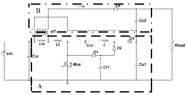
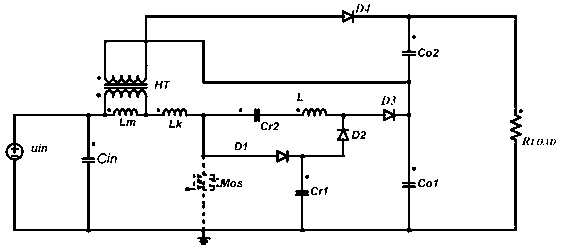
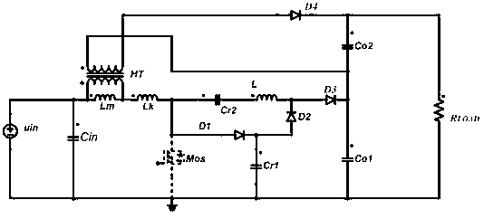
[0015] Such as figure 1 As shown, the present invention is composed of a novel Boost circuit (circuit A) with voltage doubling function and a flyback converter (circuit B). The Boost circuit and the flyback converter share an input terminal, which simplifies the circuit structure and can The leakage inductance of the transformer is fully utilized to improve the system efficiency; the output terminals of the two circuits are connected in series to increase the overall voltage gain of the converter. The doubling of the output voltage of the boost circuit reduces the turn ratio of the transformer in the flyback converter and reduces the reverse turn-off voltage stress of the output diode. The reduction of the turn ratio also reduces the leakage inductance energy and improves the system performance. efficiency. The capacitor in this circuit clamps the turn-off voltage of the main power device, reducing the voltage stress of the device.

[0016] The above DC-DC DC converter, as s...


PUM


Abstract

The invention discloses a novel high-voltage gain mixing direct-current converter for a photovoltaic grid-connected micro-inverter. The novel high-voltage gain mixing direct-current converter consists of an improved novel voltage-multiplying boost converter and a flyback converter and aims at realizing high voltage gain of the converter and reducing the voltage stress of power devices. Since two circuits adopt one input end, the circuit structure is simplified; the output ends of the two circuits are in serial connection with each other to supply the power, so that the overall voltage gain of the mixing converter can be remarkably improved. Through the voltage-multiplying circuit, the voltage gain outputted by the traditional boost circuit can be multiplied, the turn ratio of a transformer in the flyback converter can be reduced, and the reversed blocking voltage stress of an output diode D4 can be effectively alleviated; the leakage inductance energy of the transformer can be recycled through the voltage-multiplying boost circuit, and the system efficiency can be improved; the voltage stress of the main power device can be reduced through a capacitor clamping circuit in the circuit.

Description

technical field [0001] The invention relates to a high voltage gain hybrid DC converter, specifically, it is jointly composed of a novel Boost circuit (circuit A) with a voltage doubling function and a flyback converter (circuit B). Background technique [0002] Limited by the output voltage of photovoltaic modules, current grid-connected photovoltaic power generation systems mostly use modules in series for power supply, but the difference in characteristics between different modules will reduce the power generation effect of photovoltaic devices, and local shading will aggravate this problem. The micro-inverter can realize the grid-connected power generation of a single photovoltaic module, which is an effective means to solve this problem. Among them, the high-voltage gain DC converter increases the output voltage of the lower module to 350V-400V to realize the grid-connected power generation of the inverter, which is the core component of the micro-inverter. [0003] At...

Claims


Application Information

Patent Timeline
Patent Type & Authority Applications(China)
IPC IPC(8): H02M3/315
CPCY02E10/56
Inventor 张超徐磊李国庆周强
Owner JIANGSU UNIV
Why Eureka
Try Eureka