Macro and micro-driving type linear piezoelectric motor and driving method thereof

A piezoelectric motor and macro-micro drive technology, applied in the field of motor research, can solve the problems of inaccurate realization and limited application scope, and achieve the effects of simple processing, convenient design and debugging, and simple and compact structure.

Active Publication Date: 2013-09-04
SOUTH CHINA AGRI UNIV
View PDF4 Cites 11 Cited by
  • Summary
  • Abstract
  • Description
  • Claims
  • Application Information

AI Technical Summary

Problems solved by technology

[0003] Due to its small size, high displacement resolution, fast response speed, large output force, and high energy conversion efficiency, the piezoelectric ceramic drive has become an ideal drive element for precise positioning, but its stroke is only tens of microns, so its application range restricted
[0004] At present, there is a concept of macro-micro drive in the existing technology, that is, on one motor, large-stroke high-speed movement and high-resolution precision movement can be realized at the same time, but this concept cannot be accurately realized in practical applications.

Method used


Image

  • Macro and micro-driving type linear piezoelectric motor and driving method thereof
  • Macro and micro-driving type linear piezoelectric motor and driving method thereof
  • Macro and micro-driving type linear piezoelectric motor and driving method thereof

Examples


Embodiment 1

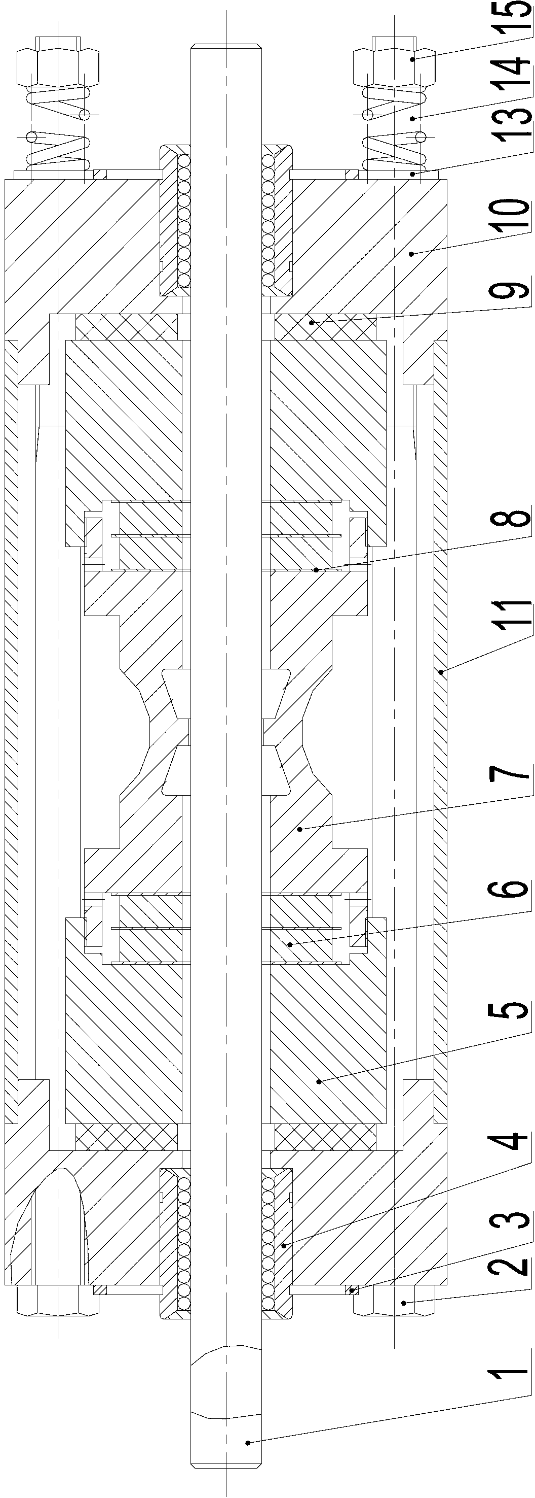
[0042] Such as figure 1 As shown, a macro-micro-driven linear piezoelectric motor includes a frame, a driving vibrator, a mover 1, and a preload mechanism for locking the frame, driving the vibrator, and the mover 1 and adjusting the preload. The frame in the example includes a frame plate 11, a frame cover 10, and the pre-tightening mechanism includes fastening bolts 2, rubber washers 9, flat washers 13, cylindrical springs 14 and fastening nuts 15 and the like. The pre-tightening mechanism gives a certain pre-tightening force to the motor stator by changing the feeding depth of the fastening bolt 2 and the elastic deformation of the rubber washer 9 . Rolling linear ball bearings 4 are provided at both ends of the frame, and a circlip 3 is provided between the bearing 4 and the frame cover 10. The mover 1 is a constant-radius cylindrical guide rod, and the mover 1 passes through the two bearings and the drive vibrator. The hole in the middle is guided by rolling linear ball ...

Embodiment 2

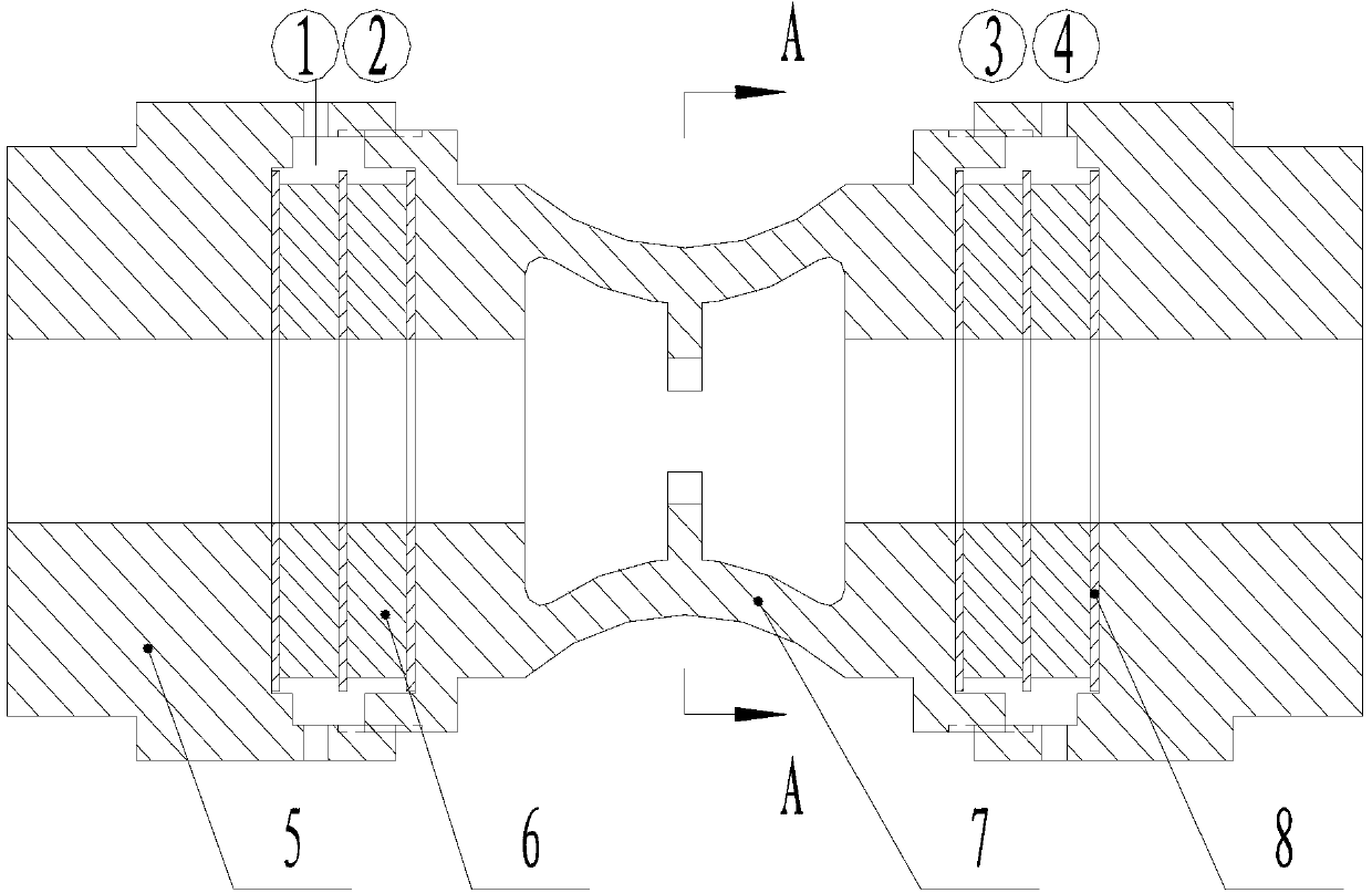
[0058] This embodiment has the same structure as Embodiment 1 except for the following features: the driving vibrator of this embodiment is as follows Figure 6 , 7, 8, the metal elastic body 25 at each end of the driving vibrator is divided into two parts, and the outer surface of one end close to the frame cover is a hexagonal prism structure, which can be used as a wrench position when fixing, and is compatible with micro-displacement amplification The outer surface of one end connected by the elastic body is a cylinder, and the outer surface is provided with an external thread, and the micro-displacement amplifying elastic body 27 is provided with an internal thread, and the internal thread is provided with a gap for leading the lead wire out of the micro-displacement amplifying elastic body. The terminal 28 is drawn out from this notch. The piezoelectric ceramic disc 26, the metal elastic body 25 and the micro-displacement amplifying elastic body 27 are fastened together...

Embodiment 3

[0061] This embodiment has the same structure as Embodiment 2 except for the following features: the driving vibrator of this embodiment is as follows Figure 9 , 10 , 11, the outer surface of the metal elastic body 35 in the driving vibrator is a cylinder, and at the same time, the metal elastic body 35 and the micro-displacement amplification elastic body 37 are all provided with bosses, and the two pass through the fastening bolt 33 and the fastening nut 34 connect. In practical applications, in order to facilitate the connection of bolts, the micro-displacement amplifying elastic body and the metal elastic body can be designed as variable-diameter cylinders as required. A convex tooth 312 is provided in the inner middle of the micro-displacement amplifying elastic body hole 37, and the convex tooth 312 is in frictional contact with the mover during the driving process, and the contact area between the two is the driving area.

[0062] The installation process of the driv...


PUM


Abstract

The invention discloses a macro and micro-driving type linear piezoelectric motor and a driving method thereof, and relates to the field of the ultrasonic motor and micro driving. The motor comprises a rack, a driving vibrator, an active cell and a pre-tightening mechanism, wherein the driving vibrator comprises a metallic elastomer, a micrometric displacement amplification elastomer and a piezoelectric element; the two symmetrical convex teeth on the inner side of the micrometric displacement amplification elastomer are in frictional contact with the active cell; and the piezoelectric element is polarized along the thickness direction. The motor macro driving method is characterized in that two longitudinal standing waves of which the phase difference is 90 degrees, the frequencies are closed, and the type are the same are stimulated by the vibrator under the action of the alternating current of which the phase difference is 90 degrees; after the standing waves are combined, an elliptic movement locus is formed on the convex tooth part; and under the pre-tightening force action, the active cell generates the macro linear movement. According to the micro-driving method, direct-current high voltage is applied to the piezoelectric element, the vibrator generates static deformation, and the two symmetrical convex teeth on the inner side of the micrometric displacement amplification elastomer clamp the active cell and the micro linear movement is generated. According to the invention, the macro driving and the micro driving are simultaneously realized on one motor, and the invention has the characteristics of simple structure and reliability in working.

Description

technical field [0001] The invention relates to the field of motor research, in particular to a macro-micro-driven linear piezoelectric motor and a driving method thereof. Background technique [0002] With the rapid progress of the IC manufacturing process and the urgent demand for tiny chips in the market, the chip integration level is increasing day by day, the I / O density is getting higher and higher, the chip size, chip lead spacing and pad diameter continue to decrease, and the chip packaging industry The rapid development puts forward extremely high requirements on the positioning accuracy, motion speed and acceleration of packaging equipment. However, the improvement of positioning accuracy and movement speed is contradictory. The increase of movement speed and acceleration will increase the inertial force of the mechanism, and the frequency of inertial force changes will also increase. The system is prone to elastic deformation and vibration, which will damage the m...

Claims


Application Information

Patent Timeline
IPC IPC(8): H02N2/04
Inventor 张铁民曹飞梁莉黄沛盛
Owner SOUTH CHINA AGRI UNIV
Why Eureka
Try Eureka