Vacuum package machine

A technology of vacuum packaging machine and frame, which is applied in the directions of packaging, transportation packaging, transportation and packaging, etc., and can solve the problems of follow-up procedure confusion and lower reliability

Active Publication Date: 2013-09-11
TIANJIN SAINTEAGLE WELDING CO LTD
View PDF8 Cites 11 Cited by
  • Summary
  • Abstract
  • Description
  • Claims
  • Application Information

AI Technical Summary

Problems solved by technology

However, if the follow-up program can only process one product at a time, such as the program of packing and gluing the product, it is easy to cause confusion to the follow-up program if a certain program outputs multiple products at one time. Increase the buffer program, increase the complexity and manufacturing cost of the equipment, and reduce the reliability

Method used


Image

  • Vacuum package machine
  • Vacuum package machine
  • Vacuum package machine

Examples


Embodiment 1

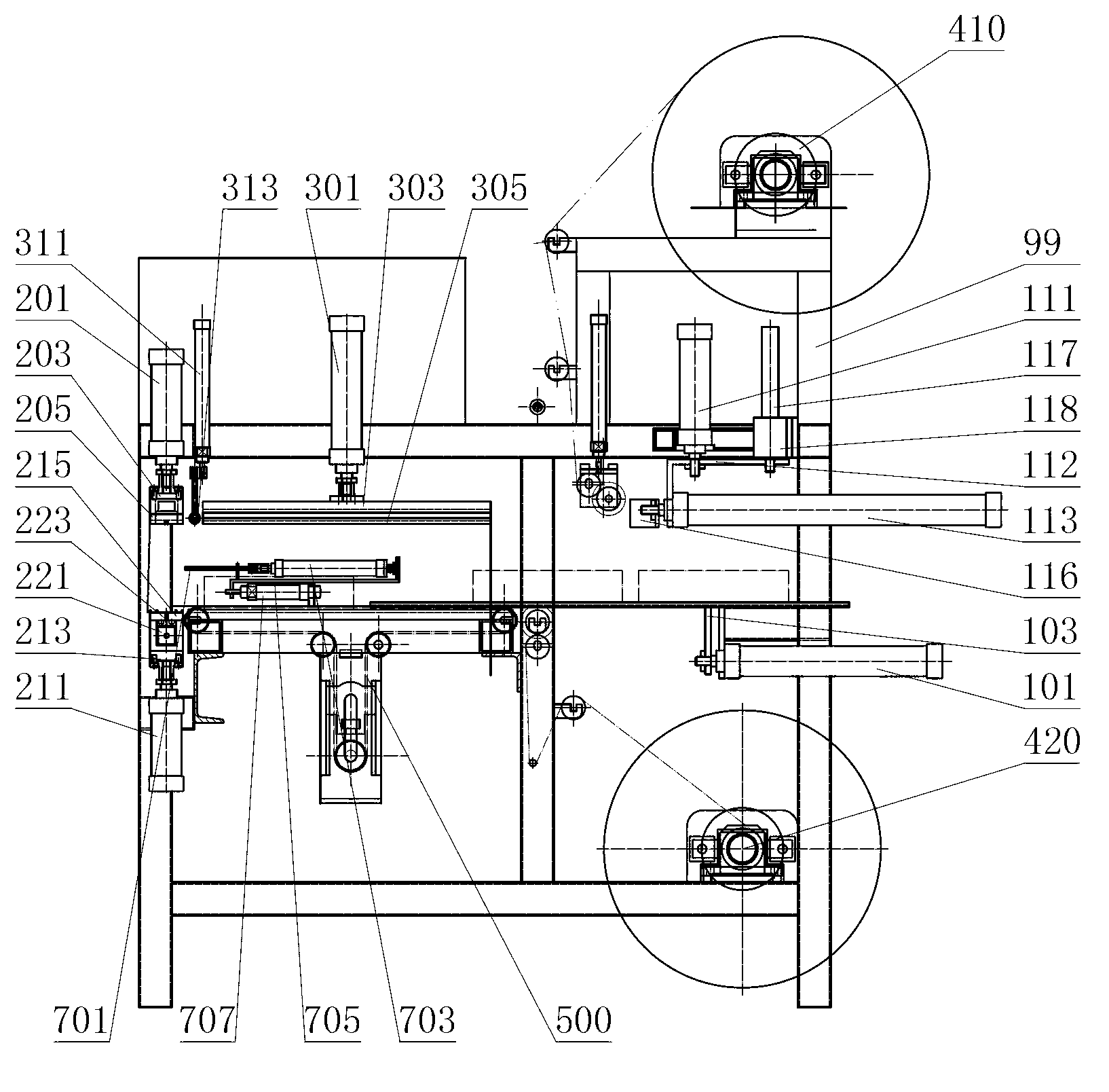
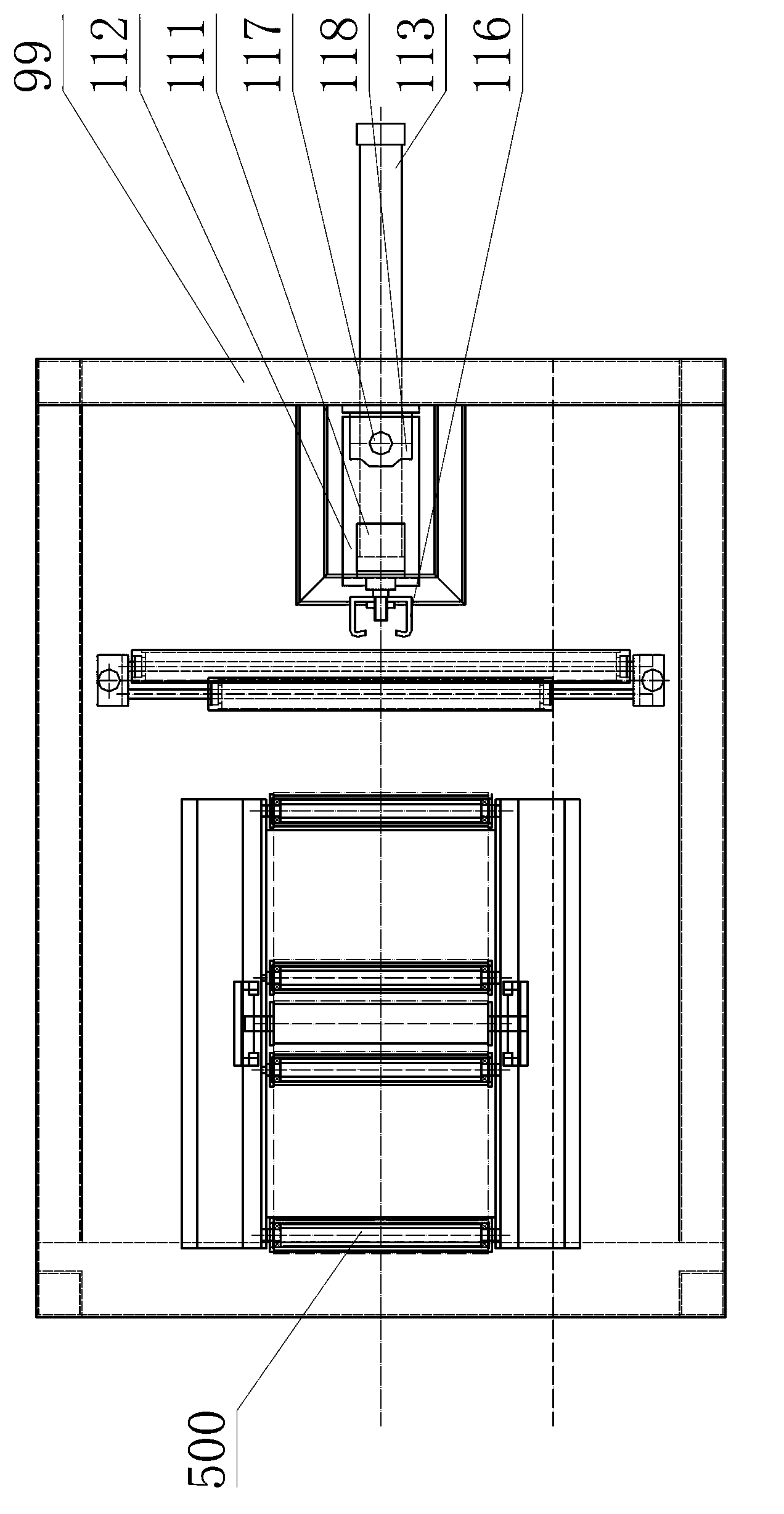
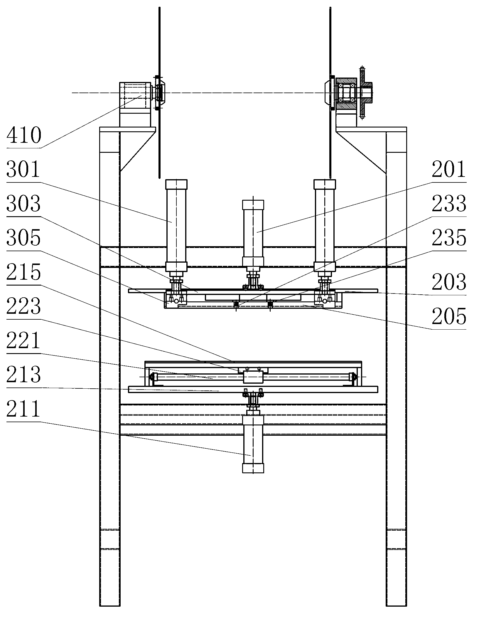
[0050] see Figure 1-3 ,

[0051] A vacuum packaging machine, including a welding wire reel feeding mechanism located at the most upstream and a finished product conveying device located at the most downstream, and also includes a film sealing device and a film supply device, the film supply device includes an upper film supply device and a lower film supply device, The upper film feeding device is located at the upper part of the frame, the lower film feeding device is located at the lower part of the frame, the film sealing device includes a front sealing film device and a side sealing film device, the front sealing film device is set at the exit of the vacuum packaging machine, the front sealing film The device is also equipped with a film cutting device, the side sealing device is arranged upstream of the front sealing device, the upstream of the front sealing device is also provided with a vacuum device, and the upstream of the front sealing device is provided with a semi...

Embodiment 2

[0076] like Figure 4 As shown, most of this embodiment is the same as Embodiment 1, the only difference is that the installation method of the lamination cylinder of the lamination device is different, including two structures:

[0077]The first type of mechanism: the film-pressing cylinder 311 is hinged at the tail or the middle part on the frame. The laminating roller 313 is still connected, and a bracket is provided under the cylinder, so that the head of the cylinder is still in the direction obliquely downward (towards the lower right in the figure) when the cylinder shrinks. At step (10) of the action principle, the laminating cylinder stretches out, and first pushes the laminating roller to move upwards to the packaging film. While the film cylinder stretches out, the lamination cylinder swings, and the lamination roller rolls to the right on the upper packaging film, thereby squeezing out the air between the upper packaging film and the lower packaging film. In step...

Embodiment 3

[0080] Most of this embodiment is the same as Embodiment 1, the only difference is that the lamination device does not compress the space between the upper packaging film and the lower packaging film through the lamination roller, and the lamination process is a belt driven by the lamination cylinder. It can be done by elastic laminating board, and the following two mechanisms can be used:

[0081] The first organization:

[0082] like Figure 5 As shown, the film-pressing cylinder 311 is fixedly connected to the frame 99, the piston rod of the film-pressing cylinder is fixedly connected to the film-pressing plate 315, and the movement of the film-pressing plate is also guided by a linear guide (the linear guide is omitted in the figure). The shape of the laminated plate can be a flat plate or a downwardly protruding arc. In step (10), when the cylinder is stretched out, the tail of the pressure film plate first touches the upper and lower packaging films, and then during th...


PUM


Abstract

The invention relates to a vacuum package machine which comprises a welding wire disc feeding mechanism and a finished product delivery device and further comprises a film sealing device and a film supplying device. The film supplying device comprises an upper film supplying device and a lower film supplying device. The upper film supplying device is located on the upper portion of a machine frame and the lower film supplying device is located on the lower portion of the machine frame. The film sealing device comprises a front film sealing device and a side film sealing device. The front film sealing device is arranged on the outlet portion of the vacuum package machine. A film cutting device is further arranged on the front film sealing device. The side film sealing device is arranged on the upstream of the front film sealing device, a vacuum pumping device is further arranged on the upstream of the front film sealing device, and a semi-finished product delivery device is arranged on the upstream of the front film sealing device. The vacuum package machine has the advantages that the structure that a vacuum pumping tube is stretched into a bag is adopted so that a singe package bag can be vacuumized, the air pumping volume each time can be reduced to a great extent, and the operation efficiency of vacuum package can be improved; meanwhile, only one package bag is output backwards each time, so that the burden brought to following devices due to one-time input of a plurality of welding wire package bags is reduced.

Description

technical field [0001] The patent belongs to the technical field of vacuum packaging of trays, and in particular relates to a vacuum packaging machine. Background technique [0002] At present, the packaging of welding wire has begun to adopt the form of vacuum packaging. The main purpose is to reduce the air content in the packaging bag, and to isolate the welding wire from the air to avoid oxidation of the welding wire and improve the storage time of the welding wire. The main method now is to put the coiled wire reel into an aluminum foil bag or a plastic bag that has been sealed on three sides, and put the bag into a vacuum packaging machine, which includes an upper cover, which will After the cover is closed, the space containing the welding wire packaging bag can form a closed cavity, the cavity is evacuated, and a vacuum is formed in the packaging bag, and then the remaining unsealed side of the packaging bag is heat-sealed. seal. However, the disadvantage of this m...

Claims


Application Information

Patent Timeline
Patent Type & Authority Applications(China)
IPC IPC(8): B65B31/06B65B51/10B65B11/50B65B61/06B65B61/24B65B35/10
Inventor 吕俊晖张国良薛继超张建国白海涛李也庚吴学兵张瑞孚
Owner TIANJIN SAINTEAGLE WELDING CO LTD
Why Eureka
Try Eureka