Adhesive composition curable with actinic energy ray, polarizer, optical film, and image display device

A technology of active energy rays and polymeric compounds, applied in the field of polarizing plates, can solve problems such as poor durability such as crack resistance, reduced transparency of the adhesive layer, and low compatibility

Active Publication Date: 2013-09-11
NITTO DENKO CORP
View PDF18 Cites 14 Cited by
  • Summary
  • Abstract
  • Description
  • Claims
  • Application Information

AI Technical Summary

Problems solved by technology

However, the polarizing plate using the above-mentioned water-based adhesive has the following problem: the size of the polarizing plate changes due to the heat of the back plate, and uneven parts are formed, so that a part of the black part of the entire screen looks white, which is so-called light leakage. (unevenness) will become apparent
However, in the combination of monomers constituting the adhesive, the compatibility between the monomers is relatively low, and there is a possibility that phase separation may occur and the transparency of the adhesive layer may decrease.
In addition, this adhesive improves the adhesiveness by softening the cured product (adhesive layer) (lowering Tg), and there is a possibility that durability such as crack resistance may deteriorate.

Method used


Image

  • Adhesive composition curable with actinic energy ray, polarizer, optical film, and image display device
  • Adhesive composition curable with actinic energy ray, polarizer, optical film, and image display device
  • Adhesive composition curable with actinic energy ray, polarizer, optical film, and image display device

Examples


Embodiment 1~7、 comparative example 1~5

[0152] Each component was mixed according to the compounding table|surface described in Table 2, and it stirred at 50 degreeC for 1 hour, and the active energy ray-curable adhesive composition of Examples 1-7 and Comparative Examples 1-5 were obtained. The components used are as follows.

[0153] (1) Radical polymerizable compound (A)

[0154] HEAA (Hydroxyethylacrylamide), SP value 29.6, Tg of homopolymer 123°C, manufactured by Kohin Co., Ltd.

[0155] N-MAM-PC (N-methylolacrylamide), SP value 31.5, homopolymer Tg 150°C, manufactured by Kasano Kosan Co., Ltd.

[0156] (2) Radical polymerizable compound (B)

[0157] ARONIX M-220 (tripropylene glycol diacrylate), SP value 19.0, homopolymer Tg 69°C, manufactured by Toagosei Co., Ltd.

[0158] Light Acrylate DCP-A (tricyclodecane dimethanol diacrylate), SP value 20.3, homopolymer Tg 134°C, manufactured by Kyoeisha Chemical Co., Ltd.

[0159] (3) Radical polymerizable compound (C)

[0160] ACMO (acryloyl morpholine), SP value...

Embodiment 8

[0169] (Production of thin polarizing film Y and production of polarizing plates using it)

[0170] In order to produce a thin polarizing film Y, first, a laminate having a 24 μm-thick PVA layer formed on an amorphous PET substrate was formed into a stretched laminate by in-air auxiliary stretching at a stretching temperature of 130°C, and then dyed The stretched laminate is made into a colored laminate, and further stretched in boric acid water at a stretching temperature of 65 degrees to make the colored laminate integrated with the amorphous PET substrate to a total stretch ratio of 5.94 times, including 10 μm thick The optical film laminate of the PVA layer. By this two-stage stretching, the PVA molecules of the PVA layer formed on the amorphous PET substrate are highly oriented, and an optical film laminate comprising a PVA layer with a thickness of 10 μm can be made. The adsorbed iodine forms multi-iodide ion complexes and is highly oriented in one direction to form a h...


PUM

PropertyMeasurementUnit
glass transition temperatureaaaaaaaaaa
thicknessaaaaaaaaaa
thicknessaaaaaaaaaa

Abstract

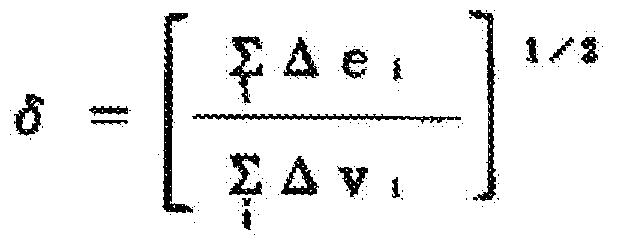
An adhesive composition curable with actinic energy rays which comprises 20-60 wt.% radical-polymerizable compound (A) that has an SP value of 29.0-32.0 (kJ / m3)1 / 2, 10-30 wt.% radical-polymerizable compound (B) that has an SP value of 18.0-21.0 (kJ / m3)1 / 2, excluding 21.0 (kJ / m3)1 / 2, and 20-60 wt.% radical-polymerizable compound (C) that has an SP value of 21.0-23.0 (kJ / m3)1 / 2, wherein the radical-polymerizable compounds (A), (B), and (C) each gives a homopolymer which has a glass transition temperature (Tg) of 60 C or above.

Description

technical field [0001] The present invention relates to an active energy ray-curable adhesive composition for forming an adhesive layer for bonding two or more members, and particularly relates to an active energy ray-curable adhesive layer for forming a polarizing plate and a transparent protective film Type adhesive composition, and polarizing plate. The polarizing plate can be used alone or in the form of an optical film laminated with the polarizing plate to form an image display device such as a liquid crystal display (LCD), an organic EL display, a CRT, or a PDP. Background technique [0002] Liquid crystal display devices are rapidly expanding the market in clocks, mobile phones, PDAs, notebook computers, computer monitors, DVD players, TVs, and the like. A liquid crystal display device is obtained by visualizing the polarization state caused by the deflection of liquid crystals, and a polarizing plate can be used based on the display principle. In particular, in ap...

Claims


Application Information

Patent Timeline
Patent Type & Authority Applications(China)
IPC IPC(8): C09J4/00C09J7/02C09J11/06G02B5/30C09J4/02
CPCC09J4/00G02F2202/28C09J7/22C09J11/06G02B5/3025G02B5/305G02F1/1306G02F1/1309C09J2203/318G02B1/14
Inventor 齐藤武士品川雅池田哲朗山崎达也大峰俊树佐竹正之后藤周作喜多川丈治宫武稔森智博上条卓史
Owner NITTO DENKO CORP
Why Eureka
Try Eureka