Sludge drying treatment system and process
A sludge drying and treatment system technology, which is applied in the directions of dehydration/drying/concentration sludge treatment, pyrolysis treatment sludge, by-product vaporization, etc., can solve the problem that continuous pyrolysis treatment, addition and removal of sludge cannot be realized The sludge process is cumbersome, difficult to produce and treat on a large scale, and achieves the effects of no latent heat loss of vaporization, low heating energy consumption, and high production efficiency
- Summary
- Abstract
- Description
- Claims
- Application Information
AI Technical Summary
Problems solved by technology
Method used
Image
Examples
Embodiment 1
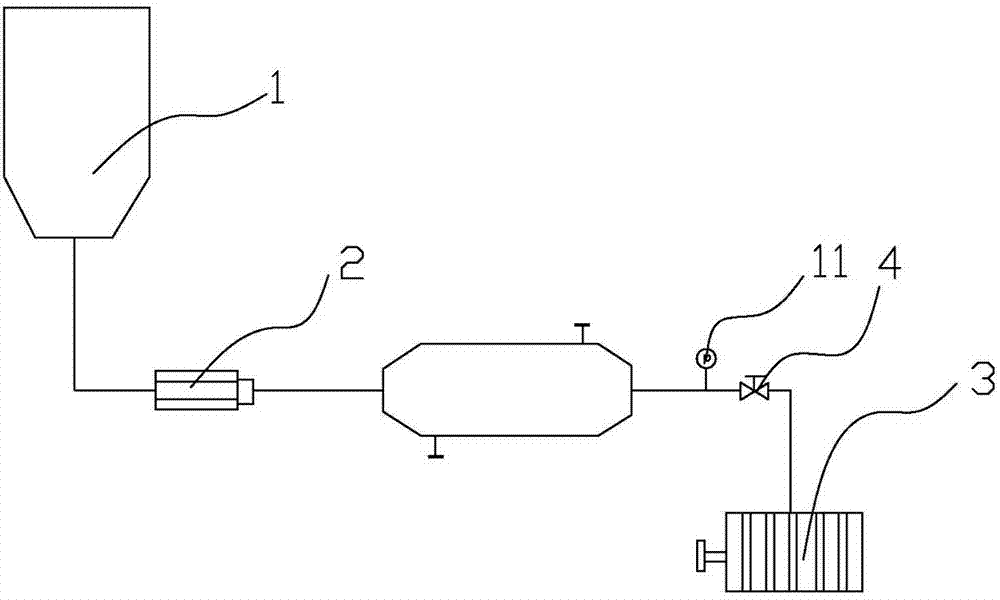
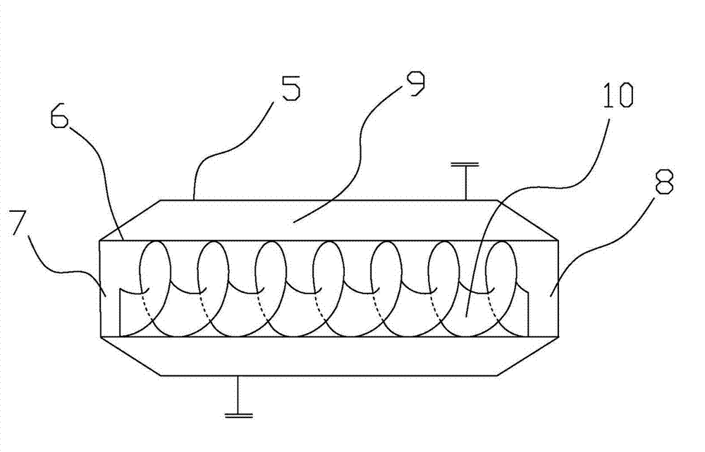
[0034] Such as figure 1 , figure 2The sludge drying treatment system shown in the figure includes a sludge storage tank 1, a high-pressure sludge pump 2, an internal spiral low-temperature pyrolysis device and a filter press 3 connected in sequence through pipelines, and the internal spiral low-temperature pyrolysis device and A pressure gauge 11 and a regulating valve 4 are arranged on the pipeline between the filter presses 3. The pressure gauge 11 is located in front of the regulating valve 4. The inner spiral low-temperature pyrolysis device includes a shell 5, which is provided with a thermostat along its length. Decomposition pipeline 6, the two ends of the pyrolysis pipeline 6 are welded to the shell 5, the opening of the pyrolysis pipeline 6 close to the high-pressure sludge pump 2 forms a material inlet 7, and the other end forms a material outlet 8, the connection between the pyrolysis pipeline 6 and the shell 5 The cavity between them forms a steam heating chamber...
Embodiment 2
[0041] Compared with Example 1, the sludge drying treatment system in this example differs in that the spiral fins 10 are inclined 45° toward the material outlet 8, and the rest are exactly the same as those in Example 1, so details are not repeated here.
[0042] A sludge drying treatment process, comprising the following steps:
[0043] (a) Add a dehydrating agent to the sludge storage tank 1 and mix it evenly and let it stand still. The amount of the dehydrating agent added is 7% of the sludge mass in the sludge storage tank 1, and the water content of the sludge in the sludge storage tank 1 The rate is 90%, and the dehydrating agent is composed of the following components in mass percentage: NaHCO 3 55%, FeCl 3 12%, 33% hydrogen peroxide with a mass concentration of 85%.
[0044] (b) The sludge mixed with the dehydrating agent in the sludge storage tank 1 is sent to the inner screw low-temperature pyrolysis device through the high-pressure sludge pump 2 for pyrolysis. ...
Embodiment 3
[0048] Compared with Example 1, the sludge drying treatment system in this example differs in that the spiral fins 10 are inclined 35° toward the material outlet 8, and the rest are identical to those in Example 1, so details will not be repeated here.
[0049] A sludge drying treatment process, comprising the following steps:
[0050] (a) Add a dehydrating agent to the sludge storage tank 1, mix evenly and let it stand still. The amount of the dehydrating agent added is 10% of the sludge mass in the sludge storage tank 1, and the water content of the sludge in the sludge storage tank 1 The rate is 98%, and the dehydrating agent is composed of the following components in mass percentage: NaHCO 3 60%, FeCl 3 20%, 20% hydrogen peroxide with a mass concentration of 85%.
[0051] (b) The sludge mixed with the dehydrating agent in the sludge storage tank 1 is sent to the inner screw low-temperature pyrolysis device through the high-pressure sludge pump 2 for pyrolysis. The slud...
PUM
 Abstract
Description
Claims
Application Information
 - R&D
- Intellectual Property
- Life Sciences
- Materials
- Tech Scout
- Unparalleled Data Quality
- Higher Quality Content
- 60% Fewer Hallucinations
Browse by: Latest US Patents, China's latest patents, Technical Efficacy Thesaurus, Application Domain, Technology Topic, Popular Technical Reports.
© 2025 PatSnap. All rights reserved.Legal|Privacy policy|Modern Slavery Act Transparency Statement|Sitemap|About US| Contact US: help@patsnap.com


