Floating auxiliary roller type overrun clutch

An overrunning clutch and auxiliary roller technology, applied in clutches, one-way clutches, mechanical equipment, etc., can solve the problems of low processing efficiency of the overrunning clutch, the number of rollers cannot be set more, and the size of the transmission equipment is large, so as to avoid mechanical failures. , the effect of reducing processing costs, maintenance and use costs

Inactive Publication Date: 2013-09-18
SOUTHWEST UNIVERSITY
View PDF5 Cites 50 Cited by
  • Summary
  • Abstract
  • Description
  • Claims
  • Application Information

AI Technical Summary

Problems solved by technology

Whether it is a ball type or a roller type overrunning clutch, setting a limit seat and an elastic element on the inner or outer ring of the overrunning clutch requires a large space in the circumferential direction, so that the number of rollers (balls) cannot be set more
Therefore, the existing overrunning clutch is not stable enough to run smoothly, and its load capacity is poor; for applications that require heavy loads, only its radial dimension must be increased, resulting in a larger size of the transmission equipment, which cannot meet the needs of modern mechanical equipment
Another is that the elastic element acts on the rolling body and restricts its reverse engagement in the circumferential direction. It acts on a point or part of the rolling body, which cannot achieve balance, making the rolling body easily deflected, resulting in jamming or poor movement. , resulting in mechanical failure
At the same time, the existing overrunning clutch needs to process the limit seat and install the elastic element, so that the processing efficiency of the overrunning clutch is low, the installation is complicated, and the cost is increased.

Method used


Image

  • Floating auxiliary roller type overrun clutch
  • Floating auxiliary roller type overrun clutch
  • Floating auxiliary roller type overrun clutch

Examples


Embodiment Construction

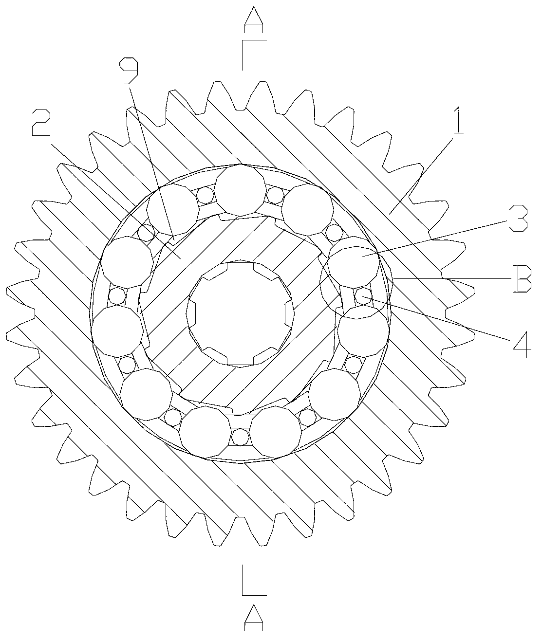
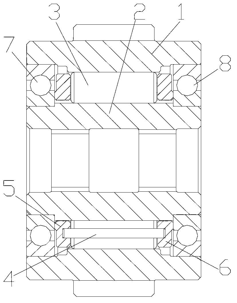
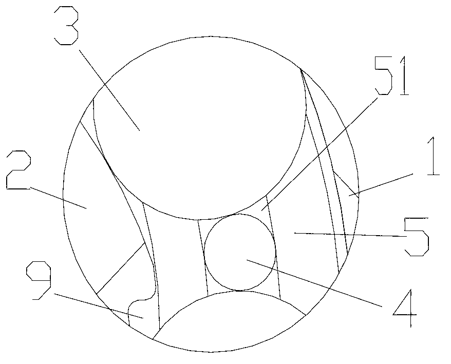
[0021] figure 1 It is a schematic diagram of the structure of the present invention, figure 2 for figure 1 Sectional view along A-A direction, image 3 for figure 1 The enlarged view along B, as shown in the figure: the floating auxiliary roller overrunning clutch of this embodiment includes an outer ring 1, an inner ring 2 and a rolling body 3, and the outer ring 1 and the inner ring 2 are formed for contact with The meshing space 9 where the rolling elements engage or disengage also includes an auxiliary roller assembly, which at least includes auxiliary rollers parallel to the axis of the overrunning clutch (also the axis of the outer ring 1 and inner ring 2) and spaced from the rolling elements 3. The rollers 4 are arranged at intervals, that is, an auxiliary roller 4 is arranged between every two rolling elements 3; Circumferential direction) The rolling bodies 3 on both sides are in contact with the outer circle, and the auxiliary roller 4 is set in a manner that ca...


PUM


Abstract

The invention discloses a floating auxiliary roller type overrun clutch which comprises an outer ring, an inner ring, rolling bodies and auxiliary rollers, wherein engagement spaces used for being engaged with or separated from the rolling bodies are formed between the outer ring and the inner ring; the auxiliary rollers are parallel to an axial line of the overrun clutch and are spaced from the rolling bodies; and the auxiliary rollers are arranged between the rolling bodies in such a way that the auxiliary rollers can move in a circumferential direction of the overrun clutch. According to the floating auxiliary roller type overrun clutch, the processing of a limiting seat is avoided, the processing process is simplified, the working efficiency is improved, and the processing cost is reduced; as the auxiliary roller structure is adopted, the axial length of the overrun clutch and the rolling bodies can be theoretically infinitely prolonged, the engagement length is prolonged, the bearing capacity of the overrun clutch is increased, the radial size of the overrun clutch under higher bearing capacity is reduced, and the service life of the overrun clutch is prolonged; and meanwhile, the probability of imbalance caused by application of a pretension force to point contact of each roller in the prior art is removed, thereby enabling each roller to keep parallel to the axial line of the inner ring.

Description

technical field [0001] The invention relates to a clutch device for motor vehicles and mechanical transmission, in particular to an overrunning clutch. Background technique [0002] The overrunning clutch is a basic component that appears with the development of power products. It is an important component used for power transmission and separation between the prime mover and the working machine or between the driving shaft and the driven shaft inside the machine. It is mainly a device with a self-clutching function by utilizing the speed change of the main and driven parts or the transformation of the rotation direction. In practice, most of them are clutches that use the meshing of teeth, the meshing of ratchet-pawl, or the wedging action of rolling elements and wedges to transmit motion or torque in one direction. [0003] Roller overrunning clutches are widely used in higher speed occasions because of their uniform and stable transmission and large load-carrying capacit...

Claims


Application Information

Patent Timeline
Patent Type & Authority Applications(China)
IPC IPC(8): F16D41/064
Inventor 薛荣生郝允志周黔
Owner SOUTHWEST UNIVERSITY
Why Eureka
Try Eureka