Dielectric constant measuring device

A technology for measuring device and permittivity, which is applied in the direction of measuring device, measuring electrical variables, measuring resistance/reactance/impedance, etc. It can solve problems such as use limitations, achieve wide applicability, high sensitivity, and improve measurement accuracy and measurement speed. Effect

Active Publication Date: 2013-09-18
SICHUAN UNIV
View PDF14 Cites 13 Cited by
  • Summary
  • Abstract
  • Description
  • Claims
  • Application Information

AI Technical Summary

Problems solved by technology

When measuring the dielectric constant of this patent application, the dielectric material needs to be in direct contact with the microstrip transmission line, which is usually only used to test non-corrosive solid dielectric materials, and its use is greatly restricted

Method used


Image

  • Dielectric constant measuring device
  • Dielectric constant measuring device
  • Dielectric constant measuring device

Examples


Embodiment 1

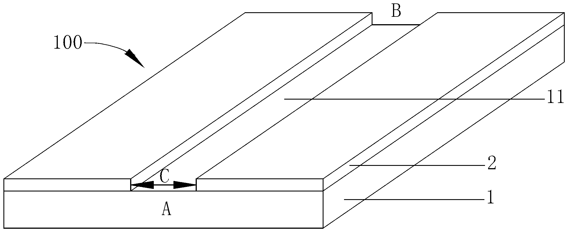
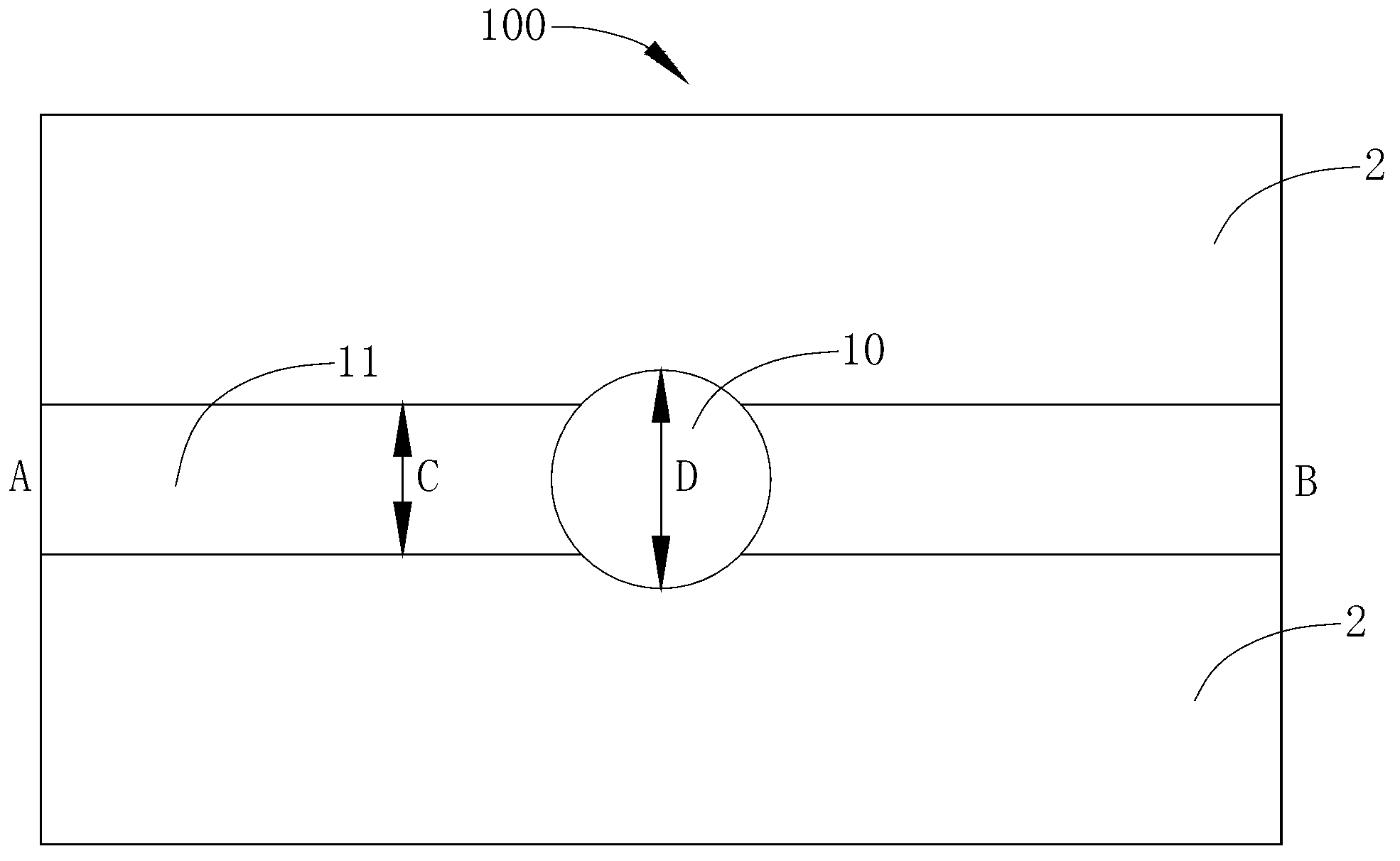
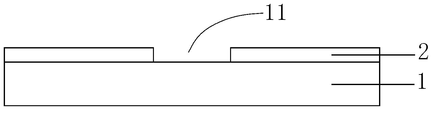
[0038] The dielectric constant measuring device of the present invention includes a slotted wire structure 100, and the two ends of A and B of the slotted wire structure 100 are respectively provided with signal interfaces for connecting testing instruments and transmitting testing signals. Such as figure 2 , image 3 with Figure 4As shown, a hole 10 is provided in the groove line structure 100 in this example, and the hole 10 is located in the groove line 11 for placing a container 12 containing the material to be tested. The slot line structure 100 is symmetrical, and the hole 10 is arranged on the center line of the slot line 11 and is located at its symmetrical center. In this example, the measured medium is a liquid, and the container 12 is a commonly used test tube. Its cross-sectional shape is circular, and the diameter D of the hole 10 is large enough, so that the measured liquid medium contained in a test tube of the same size can fully affect the groove line stru...

Embodiment 2

[0040] The groove line structure 100 of this example is the same as that of Embodiment 1, the difference is that the cross-sectional shape of the hole 10 in this example is a square, such as Figure 5 shown. As long as the side length E of the hole 10 is greater than the width C of the groove line, the measured liquid medium contained in the matched container 12 can fully affect the scattering parameters of the groove line structure 100 and meet the test requirements.

Embodiment 3

[0042] Such as Image 6 As shown, the slot line structure 100 in this example is placed in the shielding box 200 , and the two signal interfaces 201 are placed outside the side walls at both ends of the shielding box 200 . This structure has a very strong anti-interference ability, can effectively avoid the interference of external stray electromagnetic waves on the test system, and further improve the measurement accuracy. In this example, the two signal interfaces 201 include a coaxial interface and a converter, both of which adopt a coaxial interface with a characteristic impedance of 50Ω, which is a standard interface for most test instruments and signal generators. Since the coaxial interface is an unbalanced transmission interface, it does not match the balanced transmission characteristics of the slot line structure. It is necessary to use a converter between the coaxial line interface and the slot line structure for balanced / unbalanced conversion to ensure that the tes...


PUM


Abstract

The invention relates to the technical field of microwave application and discloses a dielectric constant measuring device which is not only used for measuring dielectric constant of a solid dielectric material but also used for measuring corrosive chemical solution dielectric constant. The dielectric constant measuring device comprises a groove structure. Signal interfaces are arranged at two ends of the groove structure and used for connecting a testing instrument and transmitting a testing signal. A hole is formed in the groove structure and located in a groove and used for placing a container for containing tested materials. The hole is large enough in size so that the tested materials contained in the container matched with the hole can fully affect the transmission property of the groove structure. The dielectric constant measuring device is simple in structure and high in sensitivity. A double-interface measuring method can avoid multiple solutions and is favorable for improving measuring precision and speed. The dielectric constant measuring device can be used for measuring the corrosive chemical solution dielectric constant, can achieve broadband measuring and online measuring and has wide applicability.

Description

technical field [0001] The invention relates to the field of microwave application technology, in particular to a device for measuring the dielectric constant of unknown materials by acquiring the transmission and reflection parameters of the measuring device system and performing inversion processing by adopting a slot line structure. Background technique [0002] In recent years, the application of microwave has been extended to almost every field of chemical research, such as petrochemical industry, food chemical industry, pharmaceutical chemical industry, etc., and has achieved huge economic benefits. However, due to insufficient research on the interaction mechanism between microwaves and chemical substances or chemical reactions, there are still many technical barriers to the application of microwaves in the above fields. Therefore, the research on the principle of microwaves on chemical substances has become a particularly important topic today. The study of the diele...

Claims


Application Information

Patent Timeline
Patent Type & Authority Applications(China)
IPC IPC(8): G01R27/26G01N22/00
Inventor 黄卡玛杨阳刘长军陈星郭庆功杨晓庆闫丽萍赵翔陈倩
Owner SICHUAN UNIV
Why Eureka
Try Eureka