Eureka AIR delivers breakthrough ideas for toughest innovation challenges, trusted by R&D personnel around the world.
Thin-layer fluid type low-stress polishing device
What is Al technical title?
Al technical title is built by PatSnap Al team. It summarizes the technical point description of the patent document.
A polishing device and low stress technology, applied in the field of ultra-precision optical processing, can solve the problems of medium and high frequency errors, small material removal rate, low processing efficiency, etc., achieve high polishing precision, low stress processing, and improve the effect of medium and high frequency errors
Inactive Publication Date: 2015-06-17
BEIJING INSTITUTE OF TECHNOLOGYGY
View PDF6 Cites 0 Cited by
Summary
Abstract
Description
Claims
Application Information
AI Technical Summary
This helps you quickly interpret patents by identifying the three key elements:
Problems solved by technology
Method used
Benefits of technology
Problems solved by technology
As a result, the magnetic jet polishing technology (Magnetorheological Jet Polishing, MJP), which uses a local axial magnetic field at the nozzle to stabilize the jet beam and eliminate the initial disturbance, has the advantages of good jet beam consistency, stable removal function, and high polishing accuracy. Electrorheological technology, abrasive water jet technology, etc. belong to the category of small tool polishing. During the polishing process, they can adapt to changes in the curvature of the workpiece surface, but they also have the disadvantages of relatively small material removal rate, relatively low processing efficiency, and easy to produce medium and high frequency errors.
Method used
Image
Click on the blue label to locate the original text in one second.
Reading with bidirectional positioning of images and text.
Examples
Embodiment Construction
[0027] specific implementation plan
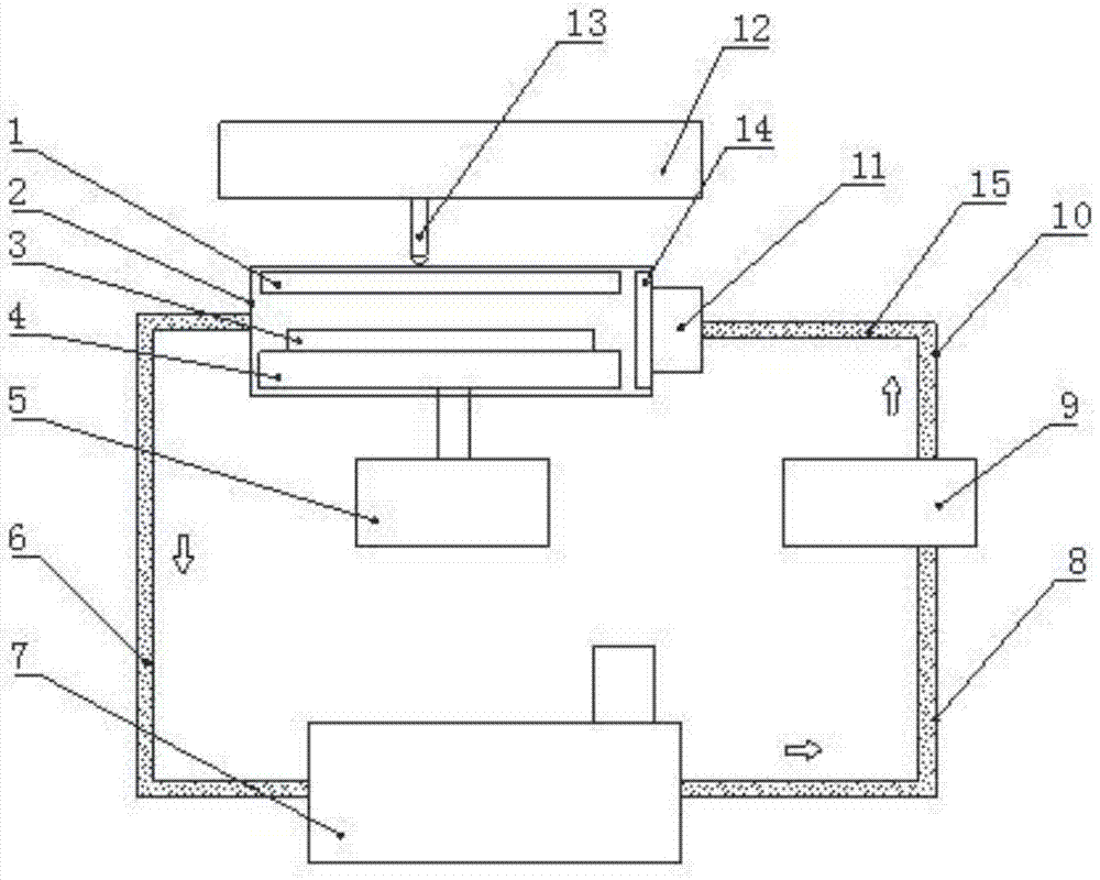
[0028] The device of the present invention will be further described below in conjunction with the accompanying drawings.
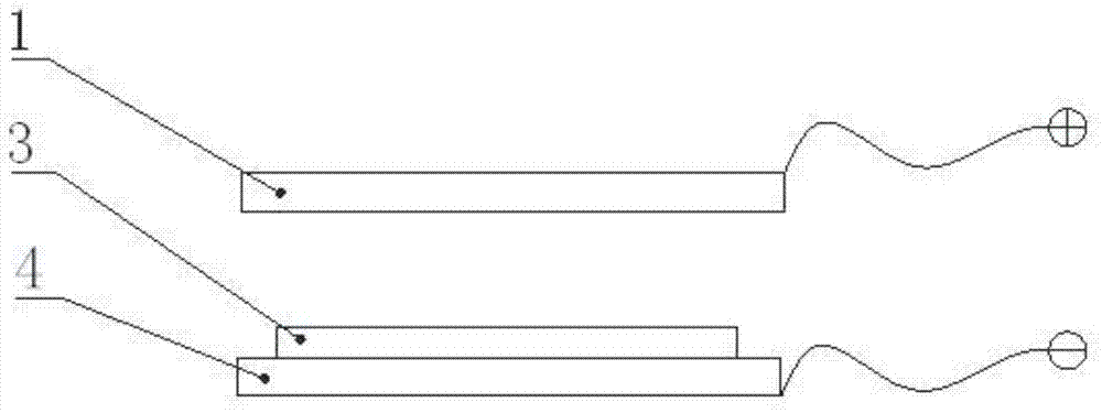
[0029] figure 1It is a structural schematic diagram of the device of the present invention, including an anode plate 1, a sealed working cabin 2, a workpiece 3, a cathode platform 4, a lifting platform 5, a polishing waste liquid 6, a waste liquid separation and stirring device 7, a first conduit 8, and a booster pump 9 , a second conduit 10, a polishing liquid collecting device 11, a two-dimensional motion platform 12, an anode probe 13, a shaping nozzle 14, and an electrorheological polishing liquid 15. The cathode platform 4 is insulated and fixed on the platform of the lifting platform 5 and connected to the cathode of the high-voltage power supply; the anode plate 1 is opposite to the cathode platform 4, and is insulated and fixed on the top of the sealed working cabin 2; the sealed working cabin 2 connects the ...
PUM
Abstract
The invention discloses a thin-layer fluid type low-stress polishing device and belongs to the field of ultra-precise optical surface machining. The device comprises a sealed working chamber, a rotary table, an anode plate, an anode probe, a cathode platform, a workpiece, a first duct, a booster pump, a lifting platform, a second duct, a moulding nozzle, a liquid collection device and the like. During working, the workpiece is fixed on the rotary table, an electric field is produced between the anode plate or the anode probe and the cathode platform, an electrorheological polishing liquid is mixed uniformly, then is boosted by the booster pump and flows into the liquid collection device through the first duct and the second duct, under the action of pressure, the liquid flows into a thin-layer area through the moulding nozzle, and under the action of the flowing power and the shearing force, surface material removing is achieved. According to the thin-layer fluid type low-stress polishing device, the problem that the workpiece is broken easily by a thin optical component due to the large positive pressure is solved, meanwhile, the phenomena that medium-and-high frequency errors remain easily due to small tool machining are improved, and the device plays an important role in optical component machining which is high in precision, free of subsurface damage and controllable in medium-and-high frequency.
Description
technical field [0001] The invention relates to a thin-layer fluid type low-stress polishing device, in particular to an electrorheological polishing fluid flow polishing device for thin optical elements, belonging to the field of ultra-precision optical processing. Background technique [0002] With the development of science and technology, modern optical systems have higher and higher requirements for the surface precision of optical components. In addition to the conventional PV, RMS and other indicators, it is also manifested in ultra-smooth, no sub-surface damage, full-band (wavefront within the effective aperture) Various spatial frequency components) error suppression, lightweight and thin, etc. The high-precision optical components required by the laser inertial confinement nuclear fusion device have strict requirements on the errors of the high, medium and low frequency bands on the surface. Generally, the Power Spectral Density function (PSD) index proposed by the...
Claims
Application Information
Patent Timeline
Application Date:The date an application was filed.
Publication Date:The date a patent or application was officially published.
First Publication Date:The earliest publication date of a patent with the same application number.
Issue Date:Publication date of the patent grant document.
PCT Entry Date:The Entry date of PCT National Phase.
Estimated Expiry Date:The statutory expiry date of a patent right according to the Patent Law, and it is the longest term of protection that the patent right can achieve without the termination of the patent right due to other reasons(Term extension factor has been taken into account ).
Invalid Date:Actual expiry date is based on effective date or publication date of legal transaction data of invalid patent.