Fracturing pulse sand filling system with ultrahigh flow conductivity and method for operating fracturing pulse sand filling system

A technology of diversion capacity and pulse, which is applied in the field of oil and gas field development and research, can solve the problems of increasing equipment and machine maintenance, repair costs, inability to realize proppant slug injection, pressure suppression of sand mixing vehicles, etc., and achieve reliable measurement and control systems , avoid damage and hysteresis effect, improve the effect of relative life

Active Publication Date: 2013-09-25
CHINA UNIV OF PETROLEUM (EAST CHINA)
7 Cites 19 Cited by

AI-Extracted Technical Summary

Problems solved by technology

At present, when the proppant is injected into the sand mixing truck, the continuous injection is basically selected, and the slug injection of the proppant cannot be realized. To realize this function, the machine needs to be switched on and off intermittently, which will be caused by repeated startup of the machi...

Abstract

The invention relates to a fracturing pulse sand filling system with ultrahigh flow conductivity. The fracturing pulse sand filling system comprises an external control unit, an internal controlled unit, an external fracturing pump truck unit, a sand mixing truck and a fluid storage tank. Fracturing sand-mixed fluid is accommodated in the sand mixing truck, fracturing base fluid is accommodated in the fluid storage tank, the external control unit controls the internal controlled unit, so that the sand-mixed fluid in the sand mixing truck and the base fluid in the fluid storage are alternately pumped into the external fracturing pump truck unit at intervals, and the sand-mixed fluid and the base fluid are finally alternately pumped into underground exploitation cracks at intervals by the external fracturing pump truck unit. The fracturing pulse sand filling system has the advantages that propping agent slugs added with fibers can be injected in a pulse manner under the control of the system, the flow conductivity of the prop cracks is greatly improved, a lag effect due to continuous opening and closing of an existing sand mixing truck is prevented, damage to the sand mixing truck is reduced, and pressure building during propping agent injection can be effectively prevented by the system.

Application Domain

Technology Topic

Image

  • Fracturing pulse sand filling system with ultrahigh flow conductivity and method for operating fracturing pulse sand filling system

Examples

  • Experimental program(5)

Example Embodiment

[0037] Embodiment 1,
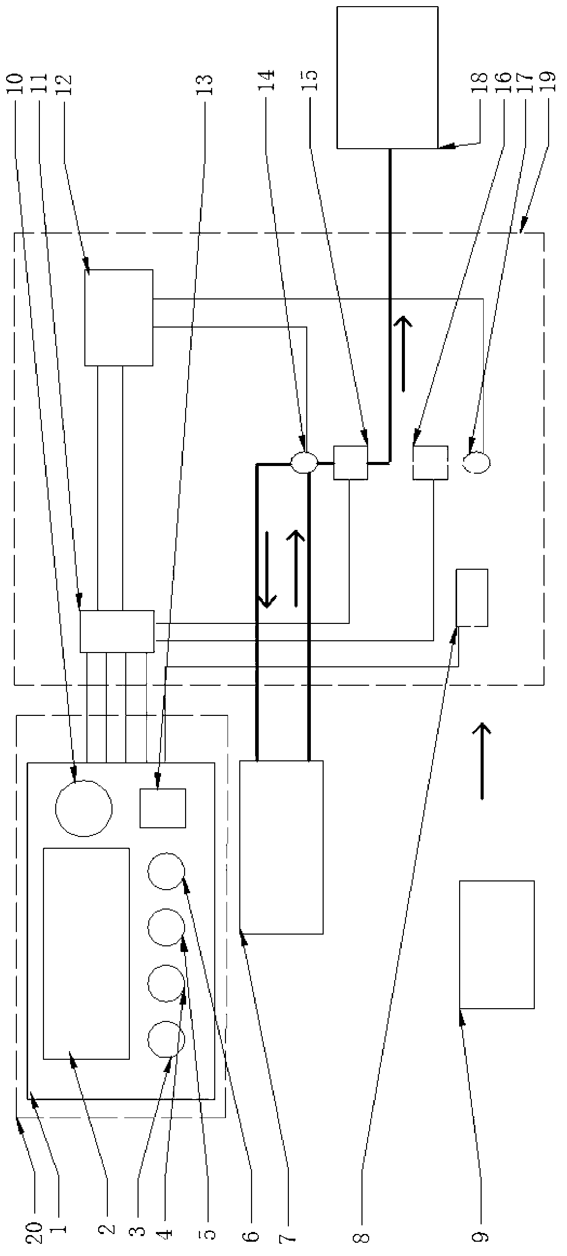
[0038] A fracturing pulse sanding system for achieving ultra-high conductivity, comprising an external control unit 20, an internal controlled unit 19, an external fracturing pump unit 18, a sand mixing vehicle 7 and a liquid storage tank 9; the sand mixing The vehicle 7 is filled with sand mixing fluid for fracturing, the liquid storage tank 9 is filled with base fluid for fracturing, and the external control unit 20 realizes the sand mixing in the sand mixing vehicle 7 through the internal controlled unit 19 The liquid and base fluid in the liquid storage tank 9 are alternately pumped into the external fracturing pump unit 18, and finally the external fracturing pump unit 18 realizes the alternate pumping of sand mixing fluid and base fluid to the middle of underground mining fractures.
[0039] The sand ratio in the sand mixing liquid is 50%.
[0040] The external control unit 20 includes a control panel 1, a display 2 installed on the control panel, a No. 1 electromagnetic flowmeter control button 3, a No. 2 electromagnetic flowmeter control button 4, and a No. 1 three-way electric ball valve control button 5 , No. 2 three-way electric ball valve control button 6, automatic manual switch button 10 and open button 13;
[0041] The internal controlled unit 19 includes a PLC controller 11, a relay 12, a No. 1 three-way electric ball valve 14, a No. 1 electromagnetic flowmeter 15, a No. 2 electromagnetic flowmeter 16, a No. 2 three-way electric ball valve 17 and an electric pump 8 The automatic manual switching button 10 is electrically connected with the PLC controller 11; the No. 1 electromagnetic flowmeter control button 3 and the No. 2 electromagnetic flowmeter control button 4 are respectively connected with the No. 1 electromagnetic flowmeter 15 through the PLC controller 11 It is electrically connected with the No. 2 electromagnetic flowmeter 16; the No. 1 electromagnetic flowmeter 15 is used to measure the delivery flow of the sand mixer 7; the No. 2 electromagnetic flowmeter 16 is used to measure the delivery flow of the liquid storage tank 9;
[0042] The No. 1 three-way electric ball valve control button 5 is electrically connected to the No. 1 three-way electric ball valve 14 respectively through the PLC controller 11 and the relay 12, and the No. 1 three-way electric ball valve 14 is connected in series to the sand mixer 7 In the feeding circuit; when the No. 1 three-way electric ball valve 14 is opened, the sand mixing fluid in the sand mixing vehicle 7 flows into the external fracturing pump unit 18 along the No. 1 electromagnetic flowmeter 15, and finally passes through the external The fracturing pump unit 18 pumps into the fracturing fracture; when the No. 1 three-way electric ball valve 14 is closed, the sand mixing fluid in the sand mixing truck 7 flows back to the sand mixing truck 7 along the feeding circuit of the sand mixing truck 7 car;
[0043] The No. 2 three-way electric ball valve control button 6 is electrically connected to the No. 2 three-way electric ball valve 17 respectively through the PLC controller 11 and the relay 12; the No. 2 three-way electric ball valve 17 is connected in series to the liquid storage tank 9 In the feeding circuit: when the No. 2 three-way electric ball valve 17 is opened, the base fluid in the liquid storage tank 9 flows into the external fracturing pump unit 18 along the No. 2 electromagnetic flowmeter 16, and finally passes through the external pressure Cracking pump unit 18 is pumped into the fracturing fracture; when the No. 2 three-way electric ball valve 17 is closed, the base fluid in the liquid storage tank 9 flows back to the liquid storage tank along the feeding circuit of the liquid storage tank;
[0044] The start button 13 is used to control the opening or closing of the whole system.

Example Embodiment

[0045] Embodiment 2,
[0046] A fracturing pulse sanding system that achieves ultra-high conductivity as described in Embodiment 1, the difference is that the No. 1 three-way electric ball valve 14 and the No. 2 three-way electric ball valve 17 are in the open or closed state Completely opposite: when the No. 1 three-way electric ball valve 14 is opened, the No. 2 three-way electric ball valve 17 is closed; when the No. 1 three-way electric ball valve 14 is closed, the No. 2 three-way electric ball valve 17 is opened. The selection parameters of the three-way electric ball valve are as follows: with AC220V as the power, the nominal diameter of the three-way electric ball valve: 101.6mm, the nominal pressure: 4MPa, the medium temperature: 20-40°C, the sealing method of the valve body is hard seal, Among them, the material of the valve body is WCB, the material of the ball is 2Cr13 (nitrided), the material of the seat sealing ring is reinforced polyvinyl chloride (PPL), the applicable temperature is -30-250 ° C, the control mode is electric switch type, and the three-way The electric ball valve is L type.

Example Embodiment

[0047] Embodiment 3,
[0048] A working method of the fracturing pulse sand adding system as described in embodiment 1, comprising the following steps:
[0049] (1) Press the start button 13 to start the fracturing pulse sand addition system;
[0050] (2) At the initial stage of fracturing, set the upper limit values ​​of the No. 1 and No. 2 electromagnetic flow meters respectively through the control button 3 of the No. 1 electromagnetic flow meter and the control button 4 of the No. 2 electromagnetic flow meter, and select the automatic mode Work, when the flow exceeds the upper limit, the system sends out an alarm, and feeds back to the PLC controller 11 according to the flow data, and the PLC controller 11 sends instructions to the No. 1 electric three-way ball valve 14 and the No. 2 electric three-way ball valve 17, and the valve Turn it down to an appropriate value. If the system has not cleared the alarm, the system will automatically switch to manual mode, and the control button 5 of the three-way electric ball valve No. 1 and the control button 6 of the three-way electric ball valve No. 2 are used to control the PLC manually. The control command is set by the device 11, respectively controls the opening size or closing time of No. 1 three-way electric ball valve 14 and No. 2 three-way electric ball valve 17, and adjusts the flow to protect the entire system. Switch the button 10 to switch it to the automatic mode and continue to work; the control button realizes the setting and adjustment of the built-in parameters of the PLC controller, thereby avoiding repeated programming of the PLC controller under different construction parameters, reducing the threshold for use, and enhancing Human-computer interaction; the system switches between manual control and automatic control, thus ensuring manual control during the pre-fluid injection stage, and manual control of shutdown in complex situations, thereby ensuring the fault tolerance rate of the system and providing a solution for complex environments. The engineering application in the system provides a guarantee; the display on the control panel of the system displays the various flow rates, sand adding speed, sand adding amount, and pressure changes of each part in the system in real time, so as to realize real-time regulation;
[0051] (3) When the No. 1 three-way electric ball valve 14 is opened, the sand mixing fluid in the sand mixing vehicle 7 flows into the external fracturing pump unit 18 along the No. 1 electromagnetic flowmeter 15, and finally passes through the external fracturing pump The machine unit 18 is pumped into the pressure fracture; when the No. 1 three-way electric ball valve 14 is closed, the sand mixing liquid in the sand mixing car 7 flows back to the sand mixing car 7 along the feeding circuit of the sand mixing car;
[0052] When the No. 2 three-way electric ball valve 17 is opened, the base fluid in the liquid storage tank 9 flows into the external fracturing pump unit 18 along the No. 2 electromagnetic flowmeter 16, and finally pumps through the external fracturing pump unit 18. into the pressure fracture; when the No. 2 three-way electric ball valve 17 is closed, the base fluid in the liquid storage tank 9 flows back to the liquid storage tank 9 along the feeding circuit of the liquid storage tank;
[0053] The external fracturing pump unit 18 realizes alternately pumping sand mixing fluid and base fluid into the middle interval of the underground mining fracture, and the opening or closing states of the No. 1 three-way electric ball valve 14 and the No. 2 three-way electric ball valve 17 are completely opposite: when When the No. 1 three-way electric ball valve 14 is opened, the No. 2 three-way electric ball valve 17 is closed; when the No. 1 three-way electric ball valve 14 is closed, the No. 2 three-way electric ball valve 17 is opened. Fluid and sand mixing fluid are pulse injected into the fracturing fractures;
[0054] (4) After the operation is completed, press the start button 13 again to close the fracturing pulse sand adding system.
[0055] The model of the sand mixing vehicle described in this embodiment is HSC210, and the maximum working pressure is 0.5 MPa. Adjust the pumping pressure of the sand mixer to the external fracturing pump unit according to the sand ratio of the sand mixing fluid; for the injection of the base fluid, the power comes from the electric pump, and its injection pressure and displacement meet the normal requirements for the external fracturing pump unit. Just supply the liquid. The alternating injection time of sand mixing fluid and base fluid is mainly determined according to the design of fracturing process parameters. According to the design of each fracturing well, the alternating injection time of sand mixing fluid and base fluid in each fracturing stage changes; Its flow rate is mainly determined by the displacement of the external fracturing pump unit. When the displacement is smaller than the displacement of the external fracturing pump unit, it cannot meet the needs of fracturing design and the expected fracturing target; When the displacement is greater than the displacement of the external fracturing pump unit, it will cause the internal pressure of the system to be suppressed, which will seriously damage the machine itself.

PUM

PropertyMeasurementUnit
Nominal diameter101.6mm
Nominal pressure4.0mPa
tensileMPa
Particle sizePa
strength10

Description & Claims & Application Information

We can also present the details of the Description, Claims and Application information to help users get a comprehensive understanding of the technical details of the patent, such as background art, summary of invention, brief description of drawings, description of embodiments, and other original content. On the other hand, users can also determine the specific scope of protection of the technology through the list of claims; as well as understand the changes in the life cycle of the technology with the presentation of the patent timeline. Login to view more.

Similar technology patents

Installation and adjustment method of infrared lenses

ActiveCN102998767AHigh-precision adjustmentHigh measurement accuracyMountingsCamera lensOptical path
Owner:BEIJING RES INST OF SPATIAL MECHANICAL & ELECTRICAL TECH

Classification and recommendation of technical efficacy words

  • High measurement accuracy
  • Low pressure loss

Screw rotor type surface profile error measurement instrument

ActiveCN102538700AAvoiding Probe Radius Compensation ProblemsHigh measurement accuracyUsing optical meansEngineeringHeadstock
Owner:HEFEI UNIV OF TECH

High performance direct shearing apparatus for large contact surfaces

ActiveCN102207436AHigh measurement accuracyLarge cut surface sizeUsing mechanical meansMaterial strength using steady shearing forcesShearing deformationNormal displacement
Owner:NANJING HYDRAULIC RES INST

Filter material

InactiveUS20090077938A1Low pressure lossHigh dust hold amountPaper/cardboardLoose filtering material filtersNatural fiberFilter material
Owner:TOYOTA BOSHOKU KK +1

Pulse pressure generation device for hydraulic oscillator

ActiveCN108868615ALow pressure lossMeet the requirements of on-site practicalityVibration devicesVibration drillingStatorEngineering
Owner:河南易发石油工程技术有限公司

Wet Flue Gas Desulfurization Device

InactiveUS20130020730A1Improve desulfurization performanceLow pressure lossFlow mixersUsing liquid separation agentExhaust gasFlue
Owner:BABCOCK HITACHI KK

Hydraulic oscillator

ActiveCN109236188ALow pressure lossEasy to replaceVibration devicesVibration drillingStatorEngineering
Owner:SINOPEC OILFIELD EQUIP CORP +1
Why Eureka
Try Eureka