Mold structure and motor

A structure and molding technology, applied in other household appliances, coatings, winding insulation materials, etc., can solve the problems of high epoxy resin viscosity, inability to make molded structures, and electromagnetic coil molding.

Inactive Publication Date: 2013-10-02
PANASONIC CORP
View PDF5 Cites 2 Cited by
  • Summary
  • Abstract
  • Description
  • Claims
  • Application Information

AI Technical Summary

Problems solved by technology

However, similar to Patent Document 2, the filler cannot be uniformly dispersed due to the high viscosity of the epoxy resin itself.
In addition, resins for prepregs cannot be used for molding electromagnetic coils of electric motors due to their low fluidity, so there is a problem that molded structures cannot be fabricated.

Method used


Image

  • Mold structure and motor
  • Mold structure and motor
  • Mold structure and motor

Examples


Embodiment approach )

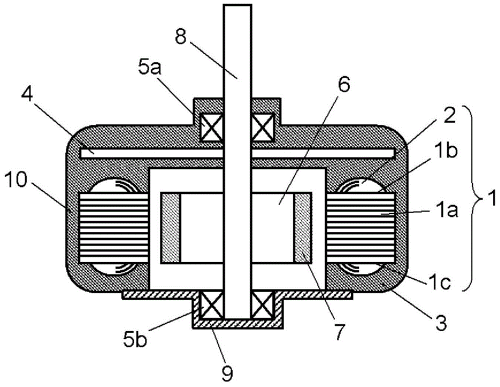
[0025] Hereinafter, for the molded structure in the embodiment of the present invention, use figure 1 Be explained. It should be noted, figure 1 In this section, a motor for home appliances such as a small air conditioner motor is described as an example. The motor is a molded structure obtained by molding an electromagnetic coil wound around an iron core using a molding resin. Forming.

[0026] figure 1 It is a sectional view showing the structure of the motor in the embodiment of the present invention.

[0027] like figure 1 As shown, the motor is composed of a stator 1, a drive circuit 4, and a rotor 6 with permanent magnets 7 on its outer periphery. The stator 1 of the motor is formed by winding a winding 2 through a bobbin in an iron core 1a; the part other than the inner peripheral surface of the iron core 1a is surrounded by a molded structure 3 formed of a molding resin. way integrally molded. At this time, the bearing housing for accommodating the bearing 5...


PUM

PropertyMeasurementUnit
viscosityaaaaaaaaaa

Abstract

This mold structure is composed of a mold resin comprising at least: a thermosetting resin; an inorganic filler having electrical insulating properties and containing at least a metal hydrate; and a dispersant. Thus, dispersibility of the inorganic filler in the mold resin is improved, enabling high filling and high fluidizing of the inorganic filler. As a result, a mold structure having high heat dissipation can be achieved by a mold resin which has high thermal conductivity and excellent moldability.

Description

technical field [0001] The present invention relates to a molded structure and a motor obtained by molding an electromagnetic coil wound around an iron core. Background technique [0002] Conventionally, there has been a strong demand for downsizing, thinning, and high output of electric motors and transformers for home appliances. In addition, considering the environment in which the machine is used, a machine with low noise and low vibration is required. [0003] In order to meet the above-mentioned requirements, there has been proposed a low-noise and low-vibration motor in which an electromagnetic coil wound on an iron core is molded using a molding resin. It should be noted that the configuration of the motor will be described in detail in the following embodiments. [0004] However, in recent years, as the environmental awareness of the market has increased, not only have motors been reduced in size, thickness, and output density, but also safety and low environmenta...

Claims


Application Information

Patent Timeline
Patent Type & Authority Applications(China)
IPC IPC(8): C08L101/00B29C45/14
CPCC08L101/00B29L2031/3481B29K2995/0013B29C45/14639C08L101/10B29K2995/0016C08L25/04C08L67/06H02K3/30
Inventor 森田畅谦近藤宪司黑住诚治
Owner PANASONIC CORP
Why Eureka
Try Eureka