Resin composition and semiconductor device

A resin composition and resin technology, applied in semiconductor devices, semiconductor/solid-state device manufacturing, semiconductor/solid-state device components, etc., can solve the problem of high viscosity of raw materials, high viscosity of resin composition, and failure to satisfy solder resistance at the same time Solve problems such as cracking and coating operability, and achieve the effect of excellent coating operability and excellent reliability

Active Publication Date: 2013-10-02
SUMITOMO BAKELITE CO LTD
View PDF6 Cites 2 Cited by
  • Summary
  • Abstract
  • Description
  • Claims
  • Application Information

AI Technical Summary

Problems solved by technology

However, such a polymer or copolymer of a butadiene compound has a good compatibility with other resins by containing a functional group, but on the other hand, the viscosity of the raw material itself becomes high
When such a raw material is used in a die attach material, if it is added in an amount that exhibits good solder crack resistance, the viscosity of the resin composition becomes high, which causes deterioration of coating workability such as stringiness
In order to further improve the performance of semiconductor devices, the demand for higher performance of die-attach materials is also increasing. There is no die-attach material that satisfies both solder crack resistance and coating workability, and it is urgently desired to achieve high-level solder reflow resistance. Die attach material with excellent performance and coating workability

Method used


Image

  • Resin composition and semiconductor device

Examples


Embodiment 1

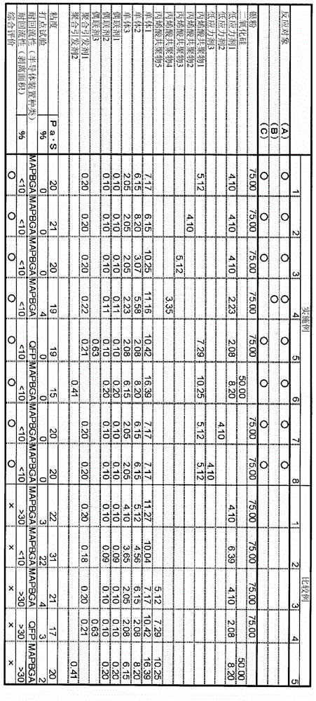
[0064] Maleic anhydride-modified polybutadiene (manufactured by Satomer, Ricobond 1731, number average molecular weight 5400) obtained by the reaction of polybutadiene and maleic anhydride as the (co)polymer (A) of the conjugated diene compound , acid anhydride equivalent 583, hereinafter referred to as low stress agent 1), as thermosetting resin (B), propoxylated bisphenol A diacrylate (manufactured by Shin Nakamura Chemical Co., Ltd., NK ester A-BPP-3, hereinafter referred to as Monomer 1), 1,6-hexanediol dimethacrylate (manufactured by Kyoeisha Chemical Co., Ltd., LIGHT ESTER1, 6HX, hereinafter referred to as monomer 2), isobornyl methacrylate (Kyoeisha Chemical Co., Ltd. Co., Ltd., LIGHT ESTER IBX, hereinafter referred to as monomer 3), as a (meth)acrylic (co)polymer (C), a (co)polymer (A) that can be combined with a conjugated diene compound. Glycidyl-based acrylic copolymers reacted with acid anhydride groups (manufactured by Toagosei Co., Ltd., ARUFON UG-4010, weight av...

Embodiment 2~8

[0066] After blending at the ratio shown in Table 1, and obtaining a resin composition in the same manner as in Example 1, evaluation was performed.

[0067] In addition, in Example 2, as the (meth)acrylic acid (co)polymer (C), a glycidyl group capable of reacting with the maleic anhydride group of the (co)polymer (A) of the conjugated diene compound was used. Acrylic copolymer (manufactured by Toagosei Co., Ltd., ARUFON UG-4035, weight average molecular weight 11000, epoxy equivalent 556, hereinafter referred to as acrylic copolymer 2); in Example 3, as (meth)acrylic acid (co) As the polymer (C), an acrylic copolymer having a hydroxyl group capable of reacting with the maleic anhydride group of the (co)polymer (A) of a conjugated diene compound (manufactured by Toagosei Co., Ltd., ARUFON UH-2000, weight average molecular weight 11000, hydroxyl equivalent weight 2806, hereinafter referred to as acrylic acid copolymer 3); in embodiment 4, as (meth)acrylic acid (co)polymer (C), ...


PUM

PropertyMeasurementUnit
particle sizeaaaaaaaaaa

Abstract

The present invention provides a resin composition having excellent coating workability while imparting reliability, including resistance to solder reflow, to a semiconductor device when used as a die attachment material or an adhesive for a heat-radiating member. This resin composition contains: a polymer or a copolymer of a conjugated diene compound having at least one functional group; a thermosetting resin; and a (meth)acrylic polymer or copolymer having a reactive functional group capable of reacting with other reactive groups.

Description

technical field [0001] The present invention relates to a resin composition and a semiconductor device. [0002] this application claims priority based on Japanese Patent Application No. 2011-017747 for which it applied to Japan on January 31, 2011, and uses the content here. Background technique [0003] In recent years, as part of environmental measures, the removal of lead from semiconductor products has progressed, and lead-free solders have begun to be used when mounting semiconductor components on substrates. When such lead-free solder is used, the solder reflow temperature becomes higher than that of conventional tin-lead solder. Therefore, as a die-attach material for bonding semiconductor elements such as ICs to supports such as metal frames or organic substrates, it is desired that peeling is less likely to occur during solder reflow than before, that is, it can sufficiently withstand the temperature of solder reflow. As the internal stress of semiconductor compo...

Claims


Application Information

Patent Timeline
Patent Type & Authority Applications(China)
IPC IPC(8): C08L101/00H01L21/52H01L23/36
CPCC08K2003/0812C08L9/00C08L13/00C08L15/00H01L23/293H01L23/3737H01L23/49513H01L24/29H01L24/83H01L2224/2919H01L2224/32225H01L2224/32245H01L2224/83192H01L2224/83862H01L2924/01029H01L2924/014H01L2924/0665H01L2924/10253H01L2924/00012H01L2924/3512H01L2924/00C08L33/068C08L33/04C08L101/02C09J115/00C09J133/04C09J201/02H01L24/04
Inventor 牧原康二村山龙一
Owner SUMITOMO BAKELITE CO LTD
Why Eureka
Try Eureka