Combined piston ring
A technology for combining pistons and piston rings, applied in piston rings, machines/engines, mechanical equipment, etc., can solve problems such as deformation, melting, and low heat resistance, and achieve increased processing costs, reduced heat load, and air-tightness excellent effect
- Summary
- Abstract
- Description
- Claims
- Application Information
AI Technical Summary
Problems solved by technology
Method used
Image
Examples
Embodiment 1
[0026] Example 1 (E1)
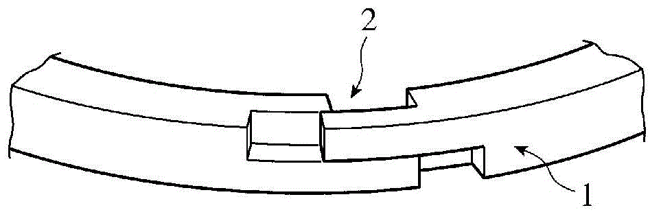
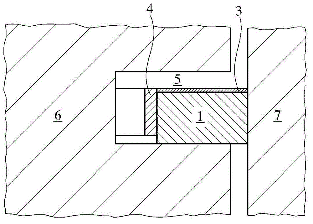
[0027] Carbon fibers are mixed with powdered polyetheretherketone (PEEK) and pellets are produced in an extruder to a predetermined amount. Then, the above-mentioned pellets were used for injection molding under predetermined conditions to a piston ring having a triple-stepped opening and a straight outer circumference. Here, the surface roughness of the side surface of the piston ring was 0.4 μm in arithmetic mean roughness (Ra). A total of 50 of the obtained piston rings were placed in a predetermined jig so that two of them overlapped and one of the sides of the piston rings was in contact with the plating solution, and the outer peripheral surface was sealed with tape to perform electroless plating of Ni-P. . The thickness of the Ni-P protective film is about 20 μm. Thus, a piston ring in the shape of a triple-step opening made of a carbon fiber-reinforced PEEK material with a Ni-P protective film formed on its side was manufactured.
[0028] En...
Embodiment 2~3
[0036] Examples 2-3 (E2-E3)
[0037] In addition to replacing the electroless plating of Ni-P with electroless plating of Cu and using Si 3 N 4 Except for the dispersed Ni-P electroless composite plating, a carbon fiber-reinforced PEEK piston ring in the shape of triple stepped openings was produced in the same manner as in Example 1. Regarding the type of protective film, the thickness of the protective film, the blowby amount at 4,000 rpm in the engine test (1), and the surface of the combustion chamber side of the piston ring before and after the test in the engine test (2) in Examples 2 and 3 The results of roughness Rz and appearance observation are shown in Table 1 together with the results of Example 1 and Comparative Example 2. In addition, the air leakage amount of each Example is the value obtained by making the air leakage amount of the comparative example 1 into 100, and performing ratio conversion respectively.
Embodiment 4
[0038] Example 4 (E4)
[0039] In addition to electroless plating instead of Ni-P, CH 4 Gas as raw material, with H 2 Except that the gas was used as a carrier gas to form a diamond-like carbon (DLC) protective film by plasma CVD, a carbon fiber-reinforced PEEK piston ring with a triple-step opening shape was produced in the same manner as in Example 1. As a method of forming the DLC protective film on one side of the piston ring, a jig similar to the jig for electroless plating used in Example 1 was used. However, use heat-resistant tape for the tape that seals the outer perimeter. Table 1 shows the test results based on the engine test (1) and the engine test (2) similarly to Examples 2 to 3.
PUM
 Abstract
Description
Claims
Application Information
 - R&D
- Intellectual Property
- Life Sciences
- Materials
- Tech Scout
- Unparalleled Data Quality
- Higher Quality Content
- 60% Fewer Hallucinations
Browse by: Latest US Patents, China's latest patents, Technical Efficacy Thesaurus, Application Domain, Technology Topic, Popular Technical Reports.
© 2025 PatSnap. All rights reserved.Legal|Privacy policy|Modern Slavery Act Transparency Statement|Sitemap|About US| Contact US: help@patsnap.com


