Micro grid monitoring and energy management device and method

An energy management device and energy management technology are applied in the field of modular monitoring and energy management devices, and can solve the problems of backward energy management methods, poor accuracy, and inability to meet the development needs of microgrids.

Inactive Publication Date: 2013-10-09
SOUTHEAST UNIV
View PDF7 Cites 46 Cited by
  • Summary
  • Abstract
  • Description
  • Claims
  • Application Information

AI Technical Summary

Problems solved by technology

[0003] Although distributed generation has outstanding advantages, its uncontrollability and random fluctuations also have a certain impact on the stability of the power system.
DG is very different from traditional power sources. For example, the discontinuity of photovoltaic and wind power generation is affected by climate, and the power generation of micro gas turbines is affected by cold and heat loads. Part of DG is connected to the grid through inverters. Small inertia may affect voltage and Frequency adversely affects, etc.
Traditional energy management devices collect real-time microgrid information through a supervisory control and data acquisition (SCADA) system for scheduling, management and control, but they do not have the real-time collection function of meteorological information required for microgrid operation, and The energy management method is outdated, with low real-time performance and poor accuracy. The control strategy is easily affected by the randomness of wind power output and load fluctuation. With the increase of DG penetration rate, it can no longer meet the development needs of microgrid

Method used


Image

  • Micro grid monitoring and energy management device and method
  • Micro grid monitoring and energy management device and method
  • Micro grid monitoring and energy management device and method

Examples


Embodiment Construction

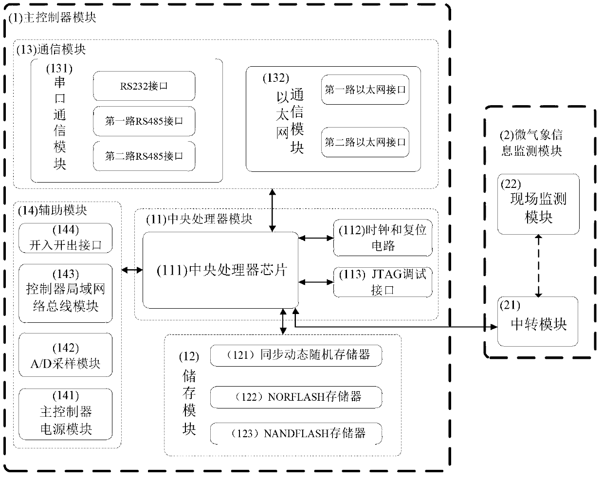
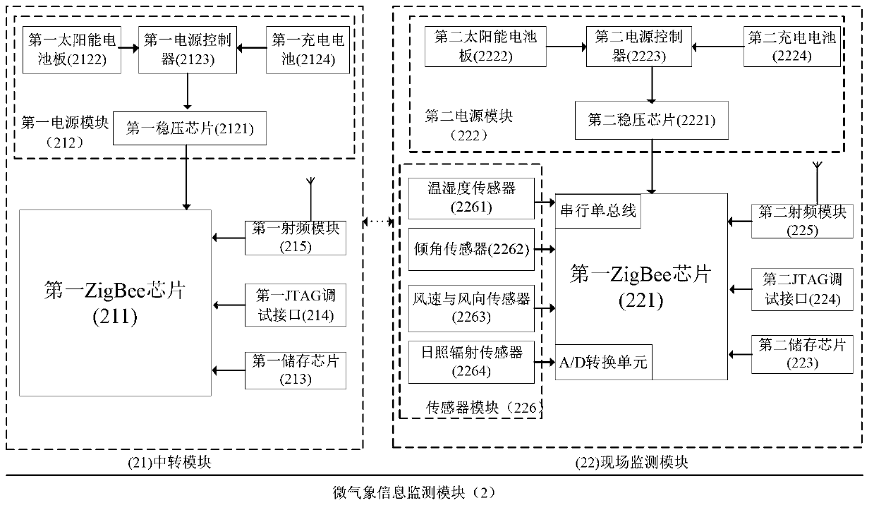
[0043] The micro-grid monitoring and energy management device of the present invention includes a main controller module 1 and a micro-meteorological information monitoring module 2. The main controller module 1 includes a central processing unit 11, a storage module 12, a communication module 13 and an auxiliary module 14. The micro-meteorological information monitoring module 2 includes a relay module 21 and an on-site monitoring module 22, as attached figure 1 Shown.

[0044] (1) Modular hardware platform

[0045] 1. Central Processing Unit Module

[0046] The central processing unit module 11 is the core of the entire device, and includes the central processing unit chip 111, the clock and reset circuit 112, and the JTAG debugging module 113.

[0047] (1) Introduction to the central processing unit chip

[0048] In addition to the advantages of fast performance and high reliability, the central processor chip 111 must also be able to perform abstract modeling of data information ...


PUM


Abstract

The invention discloses a micro grid monitoring and energy management device and method. The device comprises a master controller module and a microclimate information monitoring module. The master controller module comprises a central processing unit module, a storage module, a communication module and an auxiliary module. The microclimate information monitoring module comprises a transfer module and an in-situ monitoring module. The method includes an information monitoring and communication modeling step, a super short-term power prediction step based on microclimate monitoring, a rolling optimization step, and a micro grid energy management method based on multi-time scale coordination control. According to the device, sufficient consideration is given to convenience and real-timeness of microclimate information acquisition, and real-time monitoring of various microclimate characteristic quantities is achieved; cost is low, the convenience is high, the real-timeness is strong, and strong flexibility is achieved; the method enables step-by-step thinning to be carried out on a micro grid energy management process and enables the micro power grid monitoring and energy management device to have higher real-timeness and accuracy and to feed back and respond to wind, light and load fluctuation information in a micro grid timely.

Description

Technical field [0001] The invention belongs to the field of energy management in the microgrid, and relates to a modular monitoring and energy management device and method for optimizing the energy management of the microgrid. Background technique [0002] As the environmental pollution caused by fossil energy power generation methods and the disadvantages of large-scale power systems have become increasingly prominent, the development of clean and renewable distributed energy sources has received more and more attention and applications. Connecting distributed generators (DG) to large power grids in the form of microgrids can systematically and efficiently manage distributed power sources, improve energy efficiency, increase power supply reliability, and improve power quality. The grid adjustment based on the microgrid structure can facilitate large-scale distributed energy interconnection and access to the low- and medium-voltage power distribution system, and provides a mecha...

Claims


Application Information

Patent Timeline
Patent Type & Authority Applications(China)
IPC IPC(8): G05B19/418G08C17/02H04W84/18
CPCY02P90/02
Inventor 窦晓波王李东吴在军胡敏强徐陈成孙纯军赵波
Owner SOUTHEAST UNIV
Why Eureka
Try Eureka