Vacuum drying device and photolithographic process

A technology of vacuum drying device and photolithography process, which is used in drying solid materials, local stirring dryers, dryers for stationary materials, etc. It is difficult to volatilize and other problems, so as to reduce exposure, improve lithography accuracy, and facilitate solvent volatilization.

Inactive Publication Date: 2015-04-29
BOE TECH GRP CO LTD +1
View PDF7 Cites 1 Cited by
  • Summary
  • Abstract
  • Description
  • Claims
  • Application Information

AI Technical Summary

Problems solved by technology

At present, vacuum drying is generally completed in a vacuum drying device. The inventors of the present application have found that when using an existing vacuum drying device to dry the photoresist, because the vacuum drying is performed from the surface of the photoresist, it is easy to A hardened film is formed on the surface of the photoresist, making it difficult for the solvent in the photoresist in the hardened film to volatilize, which affects the slope angle of the photoresist (Profile)
like figure 1 As shown, it is the slope angle topography diagram of the resist when vacuum drying at room temperature; the photoresist 2 is located on the substrate 1, and since there are more solvent residues in the photoresist 2 after drying, the slope angle a of the photoresist is 20°~ 30°, it can be seen that the slope angle of the photoresist is small, which affects the photolithography accuracy

Method used


Image

  • Vacuum drying device and photolithographic process
  • Vacuum drying device and photolithographic process
  • Vacuum drying device and photolithographic process

Examples


Embodiment Construction

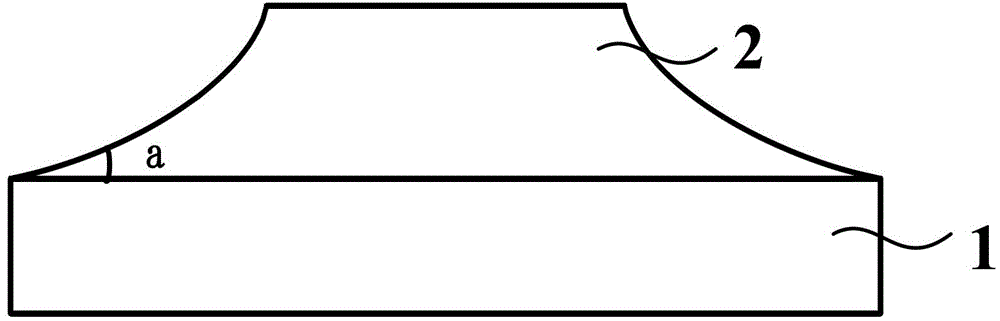
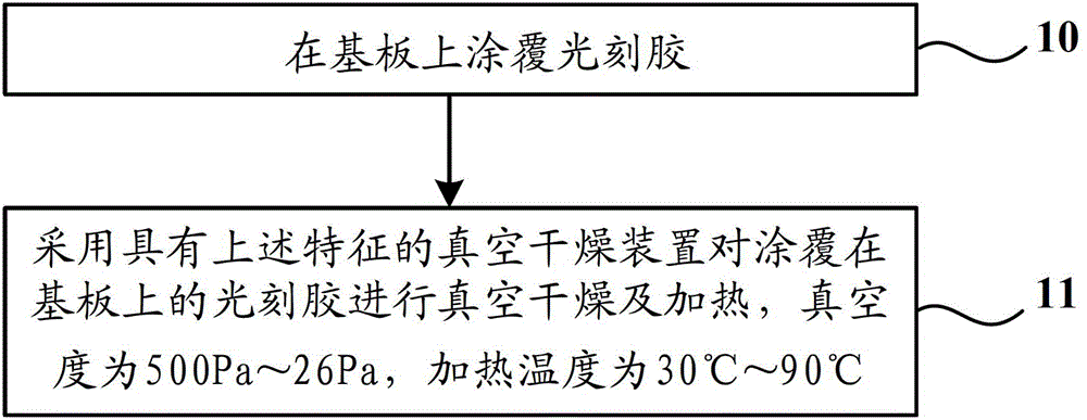
[0026] In order to reduce the residual amount of solvent in the photoresist after vacuum drying and improve the precision of photolithography, the invention provides a vacuum drying device and a photolithography process. The glue is heated to reduce the formation of a hardened film on the surface of the photoresist, thereby reducing the residual solvent in the photoresist and improving the photolithography precision.

[0027] In order to enable those skilled in the art to better understand the technical solutions of the present invention, the embodiments of the present invention will be described in detail below in conjunction with the accompanying drawings.

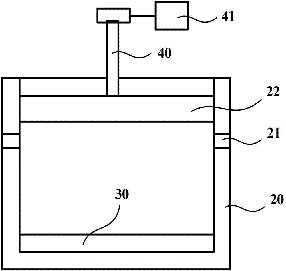
[0028] see figure 2 , is a schematic diagram of a vacuum drying device and its structure provided by an embodiment of the present invention. The vacuum drying device includes: a vacuum chamber 20 with an exhaust hole 21 and a door 22 , a vacuuming device (not shown in the figure) communicating with the exhaust hole 21 ...


PUM


Abstract

A vacuum drying apparatus comprises a vacuum chamber provided with an exhaust vent and a chamber door, a vacuum pumping apparatus in communication with the exhaust vent, and a heating assembly disposed in the vacuum chamber. A vacuum drying method by using the vacuum drying apparatus comprises: when vacuum drying is performed on a substrate coated with a photoresist, simultaneously performing the heating and vacuum drying on the photoresist, the vacuum degree preferably ranging from 26Pa to 500Pa during the drying, and the heating temperature preferably ranging from 30 to 90 degrees centigrade, so as to produce less hardening films, thereby reducing the residual amount of a solvent in the photoresist, and improving the photolithographic accuracy.

Description

technical field [0001] The invention relates to the technical field of substrate manufacturing, in particular to a vacuum drying device and a photolithography process. Background technique [0002] At present, the pattern on the substrate is generally formed by a photolithography process. The specific process is as follows: firstly, the photoresist is coated on the substrate, and then the photoresist on the substrate is vacuum-dried. Finally, after pre-baking, exposure, and development, Form the desired pattern on the substrate. [0003] Vacuum drying is an intermediate link in the photolithography process, which is used to remove the solvent in the photoresist. Therefore, the drying effect on the photoresist will directly affect the properties of the photoresist and the effects of subsequent exposure and development. At present, vacuum drying is generally completed in a vacuum drying device. The inventors of the present application have found that when using an existing va...

Claims


Application Information

Patent Timeline
Patent Type & Authority Patents(China)
IPC IPC(8): F26B9/06F26B7/00G03F7/16
CPCF26B5/04
Inventor 陆忠王军才陈巍李炳天黄丽娟
Owner BOE TECH GRP CO LTD
Why Eureka
Try Eureka