Installation structure of electric furnace induction coil for fluoride salt production

A technology of electric furnace induction coil and installation structure, which is applied in the direction of aluminum fluoride and aluminum halide, and can solve the problems of easy damage of graphite crucible and refractory materials, failure to prevent leakage of fluoride salt, explosion, etc.

Active Publication Date: 2013-10-23
周俊和 +1
View PDF3 Cites 1 Cited by
  • Summary
  • Abstract
  • Description
  • Claims
  • Application Information

AI Technical Summary

Problems solved by technology

The inventor found in experiments that when the existing intermediate frequency electric furnace heats fluoride salt, the fluoride salt will leak out from the graphite crucible, and the characteristic of fluorine element is that it can react with other substances to form fluoride, reducing its Therefore, after the conventional refractory material contacts with the leaking fluoride salt, the mel

Method used


Image

  • Installation structure of electric furnace induction coil for fluoride salt production

Examples


Embodiment 2

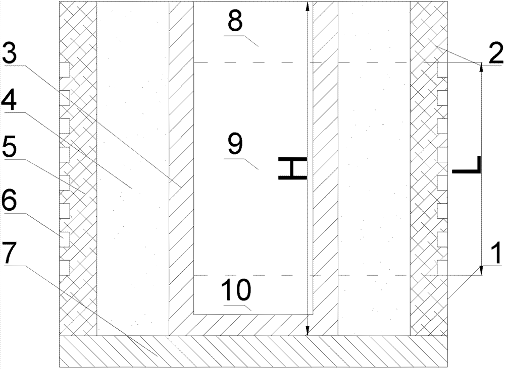
[0015] Embodiment 2 of the present invention. The installation structure of the electric furnace induction coil for fluoride salt production in the present invention is to install the induction coil layer 2 on the furnace body 1, place the graphite crucible 3 in the middle of the furnace body 1, and place the induction coil layer 2 and the graphite crucible 3 between the induction coil layer 2 and the graphite crucible Calcium oxide layer 4. Calcium oxide layer 4 selects quicklime that has just been fired, has no moisture, and has high purity. The induction coil layer 2 includes an induction coil 6 supported by refractory cement 5, and the induction coil 6 should be installed in the middle of the graphite crucible 3, and the graphite crucible 3 is divided into a feeding area 8, a reaction area 9, and a precipitation area 10; upon application According to human experiments, the installation length L of the induction coil 6 is 280-320 mm less than the height H of the graphite c...

Embodiment 3

[0018] Embodiment 3 of the present invention. The installation structure of the electric furnace induction coil for fluoride salt production, the installation structure of the electric furnace induction coil for the production of fluoride salt in the present invention, the induction coil layer 2 is installed on the furnace body 1, the graphite crucible 3 is placed in the middle of the furnace body 1, and the induction coil A calcium oxide layer 4 is placed between the layer 2 and the graphite crucible 3 . Calcium oxide layer 4 selects quicklime that has just been fired, has no moisture, and has high purity. The induction coil layer 2 includes an induction coil 6 supported by refractory cement 5, and the induction coil 6 should be installed in the middle of the graphite crucible 3, and the graphite crucible 3 is divided into a feeding area 8, a reaction area 9, and a precipitation area 10; upon application According to human experiments, the installation length L of the induct...


PUM


Abstract

The invention discloses an installation structure of an electric furnace induction coil for fluoride salt production. The installation structure comprises a furnace body (1). The installation structure is characterized in that an induction coil layer (2) is arranged on the furnace body (1); a plumbago crucible (3) is arranged in the middle of the furnace body (1); a calcium oxide layer (4) is arranged between the induction coil layer (2) and the plumbago crucible (3); an induction coil (6) of the induction coil layer (2) is arranged at the middle part of the plumbago crucible (3); the plumbago crucible (3) is divided into a feeding zone (8), a reaction zone (9) and a precipitation zone (10); the installation length L of the induction coil (6) is 200-400 mm smaller than the height H of the plumbago crucible (3). An applicant disclosed by the invention finds that no leakage is generated in the production process of fluoride salt by using calcium oxide as a refractory material; the service life of the crucible can be prolonged to more than ten days; the calcium oxide is an optimal refractory material for industrial production of the installation structure.

Description

technical field [0001] The invention relates to an installation structure of an electric furnace induction coil for fluoride salt production, and belongs to the technical field of fluoride salt recycling production. Background technique [0002] Chinese patent CN101818253 discloses a method for separation and purification of electrolytic aluminum waste, which can separate the fluoride salt in the electrolytic aluminum waste, and obtain high-purity fluoride salt (cryolite) after melting and reacting in an electric furnace. The inventor found in experiments that when the existing intermediate frequency electric furnace heats fluoride salt, the fluoride salt will leak out from the graphite crucible, and the characteristic of fluorine element is that it can react with other substances to form fluoride, reducing its Therefore, after the conventional refractory material contacts with the leaking fluoride salt, the melting point will decrease and it will also become liquid, which c...

Claims


Application Information

Patent Timeline
IPC IPC(8): C01F7/54
Inventor 邹建明阮正林
Owner 周俊和
Why Eureka
Try Eureka