Eureka AIR delivers breakthrough ideas for toughest innovation challenges, trusted by R&D personnel around the world.

Fuel injection control device of internal combustion engine

A fuel injection and control device technology, applied in fuel injection control, engine control, electrical control, etc., can solve the problems of not being able to obtain the driver's acceleration state, increase the amount of memory data and computing burden, and achieve the effect of reducing computing burden

Active Publication Date: 2013-10-23
HONDA MOTOR CO LTD
View PDF8 Cites 4 Cited by
  • Summary
  • Abstract
  • Description
  • Claims
  • Application Information

AI Technical Summary

Problems solved by technology

However, if the acceleration-time fuel correction technology described in Patent Document 1 is directly applied, the normal acceleration-time fuel correction amount is only increased for the small injection amount during lean operation, and the acceleration state desired by the driver may not be obtained.
In this regard, it is conceivable that the LAF sensor described in Patent Document 3 can be used to constantly perform feedback control so that the fuel correction amount during acceleration during lean operation can be controlled to be larger than the fuel correction amount during acceleration during normal operation. In addition to preparing the LAF sensor, there are also problems of increasing the amount of data held in the memory and the calculation load

Method used


Image

  • Fuel injection control device of internal combustion engine
  • Fuel injection control device of internal combustion engine
  • Fuel injection control device of internal combustion engine

Examples


Embodiment Construction

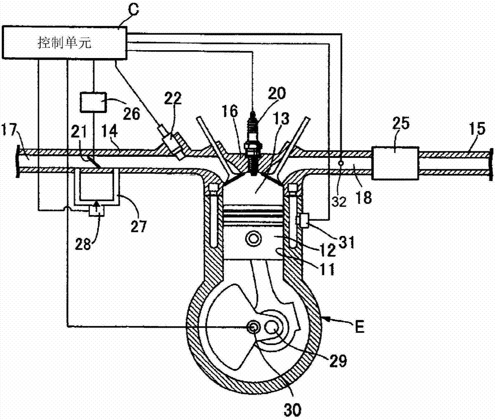
[0044] Hereinafter, preferred embodiments of the present invention will be described in detail with reference to the drawings. figure 1 It is a block diagram showing the configuration of a fuel injection control device for an internal combustion engine according to an embodiment of the present invention. A piston 12 is slidably fitted into a cylinder bore 11 of a water-cooled (or air-cooled) internal combustion engine (engine) E mounted on a motorcycle. A cylinder head 16 of the engine E is connected to an intake device 14 for supplying air-fuel mixture to the combustion chamber 13 and an exhaust device 15 for discharging exhaust gas from the combustion chamber 13 . An intake passage 17 is formed in the intake device 14 , and an exhaust passage 18 is formed in the exhaust device 15 . The catalytic converter 25 is installed between the exhaust device 15 and the exhaust passage 18 . A spark plug 20 whose tip protrudes into the combustion chamber 13 and intake / exhaust valves of...


PUM


Abstract

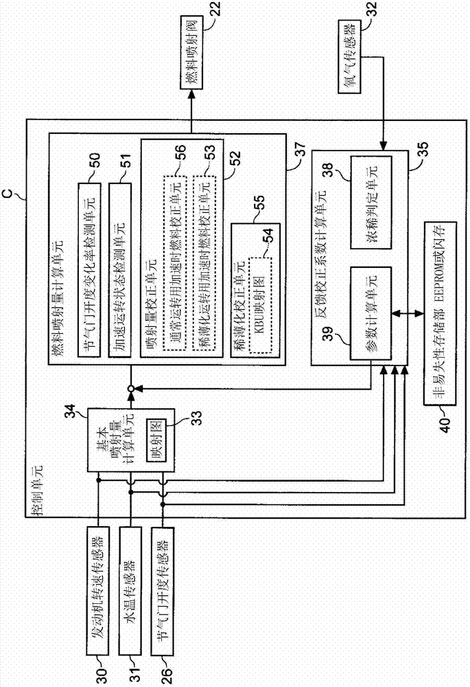
Provided is a fuel injection control device of an internal combustion engine, and the device can execute fuel correction when speeding up in rarefaction operation, and would not cause increase of components and increase of calculation load. The fuel injection control device of the internal combustion engine comprises an injection amount correction unit, and a rarefaction correction unit. The injection amount correction unit adds speeding-up fuel correction amount on preset basic injection amount when the unit detects an engine is on an accelerated operation status. When operation status of the engine breaks into a preset rarefaction area, the rarefaction correction unit multiplies basic injection amount by a rarefaction coefficient, and rarefaction operation which applies rarefaction air-fuel ratio is executed, the rarefaction air-fuel ratio being on a rarefaction side compared with a theoretical air-fuel ratio. The injection amount correction unit comprises a speeding-up fuel correction unit used for the rarefaction operation, and when the unit detects the engine is on an accelerated operation status, speeding-up fuel correction amount used for the rarefaction operation after divided by the rarefaction coefficient is obtained.

Description

technical field [0001] The present invention relates to a fuel injection control device for an internal combustion engine, in particular to a fuel injection control device for an internal combustion engine that performs air-fuel ratio feedback control and lean control based on an oxygen sensor output. Background technique [0002] Conventionally, there is known a fuel injection control device for an internal combustion engine that feedback-controls the fuel injection amount based on an output value of an oxygen sensor provided in an exhaust pipe so that the internal combustion engine is close to the stoichiometry (stoiciometry: stoichiometric ratio) state of burning. Also, in such a fuel injection control device, there is known a technique of performing an incremental correction of the fuel injection amount when the vehicle is accelerating or performing a lean operation using a lean air-fuel ratio leaner than the stoichiometric air-fuel ratio under predetermined conditions. ...

Claims


Application Information

Patent Timeline
IPC IPC(8): F02D41/14F02D41/30
Inventor 宇津木克洋小室胜纪井畑辽亮赤松俊二
Owner HONDA MOTOR CO LTD
Why Eureka
Eureka Blog
Learn More