High-speed hydrodynamic machine and composition method and assembly method of rotor of high-speed hydrodynamic machine

A high-speed fluid and power machinery technology, which is applied to the components of pumping devices for elastic fluids, liquid fuel engines, mechanical equipment, etc. The process is simple, the transmission efficiency is improved, and the sealing effect is good.

Inactive Publication Date: 2013-10-23
GREE ELECTRIC APPLIANCES INC
View PDF14 Cites 17 Cited by
  • Summary
  • Abstract
  • Description
  • Claims
  • Application Information

AI Technical Summary

Problems solved by technology

This conventional compressor structure has the following deficiencies: (1) Due to the intermediate gear speed increase box, the mechanical loss of the compressor is increased, thereby increasing the power consumption of the compressor and affecting the performance of the unit; (2) the existence of the gear box The shape and structure of the compressor are greatly increased, making the box appear bulky and heavy, and the cost also increases; (3) Due to the high speed of the centrifugal compressor, the noise during the gear speed-up process is very loud, so the noise of conventional centrifuges is common It is about 93 decibels, which makes it necessary to add additional sound insulation measures in engineering applications, resulting in increased engineering costs; (4) The motor used in conventional centrifugal compressors is a three-phase asynchronous motor, and the highest motor efficiency is about 94%. It is very difficult to further improve energy efficiency; (5) The frequency conversion of conventional centrifugal compressors belongs to the category of low-speed frequency conversion, that is, adding a frequency converter to an ordinary three-phase asynchronous motor, although this method can increase part of the load compared with the fixed freque...

Method used


Image

  • High-speed hydrodynamic machine and composition method and assembly method of rotor of high-speed hydrodynamic machine
  • High-speed hydrodynamic machine and composition method and assembly method of rotor of high-speed hydrodynamic machine
  • High-speed hydrodynamic machine and composition method and assembly method of rotor of high-speed hydrodynamic machine

Examples


specific Embodiment approach

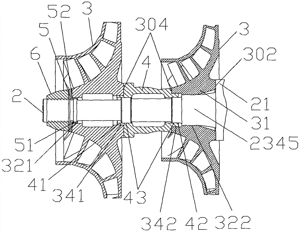
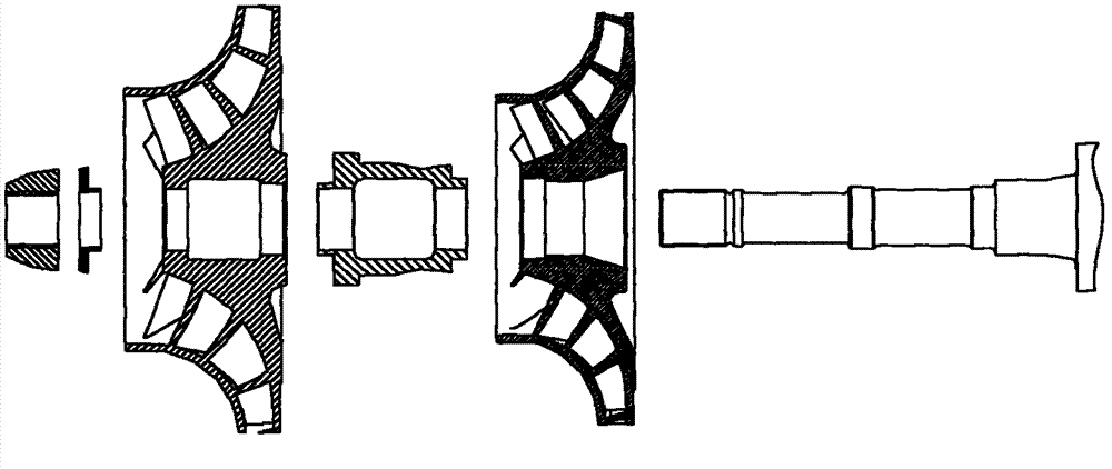
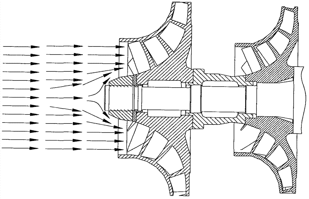
[0064] The advantage of the present invention is that it is suitable for high-speed fluid power machinery, especially high-speed centrifugal compressors with a speed above 6000 rpm, such as a high-speed centrifugal compressor with a speed of 7000 rpm to 20000 rpm. In this embodiment, the high-speed centrifugal compressor using R134a as the working medium is used as In a preferred embodiment, the working fluid can better adapt to the working range of the refrigeration centrifugal compressor at this speed. On the one hand, high-speed fluid power machinery with such a rotating speed should consider the high transmission efficiency, and on the other hand, the installation of the impeller 3 and the rotating shaft 2 should have high firmness and safety, especially to ensure that the impeller 3 and the rotating shaft 2 To maintain a high coaxiality during high-speed rotation, it is also necessary to consider easy assembly and low process cost. Taking these factors into consideration, ...


PUM


Abstract

The invention relates to a high-speed hydrodynamic machine of which the rotating speed is above 6000rpm, particularly between 7000rpm and 20000rpm. The high-speed hydrodynamic machine comprises a driving motor and a rotor, wherein the rotor comprises a driving motor rotating shaft and rotating impellers acting on fluid; and the rotating impeller are directly mounted on the driving motor rotating shaft, connected in a keyless manner, positioned together with the driving motor rotating shaft in an interference manner through hot-pressing in a radial direction, and compressed and pushes against a radial flange of the rotating shaft by a locking structure in an axial direction. In addition, the invention further relates to a composition method and an assembly method of the rotor of the high-speed hydrodynamic machine with the rotating speed above 6000rpm. According to the machine, since the rotating impellers are directly mounted on the driving motor rotating shaft, the transmission efficiency is improved greatly, the rotor is simpler to dismount simultaneously, and the impellers and the rotating shaft are good in coaxiality and sealability, and low in vibration.

Description

technical field [0001] The invention relates to a rotor of a high-speed fluid power machine, especially a rotor of a high-speed fluid power machine with a speed above 6000 rpm (such as a high-speed centrifugal compressor with a speed above 10000 rpm), and also relates to an assembly method of the rotor . Background technique [0002] At present, high-speed fluid power machinery, especially high-speed centrifugal compressors in the field of air conditioning, mostly increase the speed to the design speed through the speed-increasing gear, and drive the impeller to rotate to do work on the incoming gas, thereby increasing the gas pressure. This conventional compressor structure has the following deficiencies: (1) Due to the intermediate gear speed increase box, the mechanical loss of the compressor is increased, thereby increasing the power consumption of the compressor and affecting the performance of the unit; (2) the existence of the gear box The shape and structure of the ...

Claims


Application Information

Patent Timeline
IPC IPC(8): F04D29/28
Inventor 夏光辉赵志刚刘华张治平钟瑞兴蒋楠蒋彩云谢蓉傅鹏闫秀兵
Owner GREE ELECTRIC APPLIANCES INC
Why Eureka
Try Eureka