Motor permanent magnet fixing structure, motor permanent magnet fixing method and motor comprising the structure

A fixed structure and fixed method technology, applied in the direction of magnetic circuit shape/style/structure, magnetic circuit rotating parts, manufacturing stator/rotor body, etc., can solve problems such as increasing magnetic flux leakage coefficient, weak protection, permanent magnet throwing out, etc. , to achieve the effect of reducing the gap, avoiding magnetic flux leakage, and reducing the thickness

Inactive Publication Date: 2013-10-23
GREE ELECTRIC APPLIANCES INC
View PDF4 Cites 9 Cited by
  • Summary
  • Abstract
  • Description
  • Claims
  • Application Information

AI Technical Summary

Problems solved by technology

Carbon fiber bundles are used to bind permanent magnets. Carbon fiber bundles cannot be piled up too thick, otherwise the gap between the stator and the rotor will be too large and magnetic flux leakage will occur. However, the protection of the two ends of the permanent magnet is relatively weak and easy to An accident where a permanent magnet was thrown out
The method of installing a protective cover to protect the permanent magnet cannot avoid the defect that the gap between the stator and the permanent magnet is too large, and the protection of the permanent magnet is not reliable enough. A large gap will increase the magnetic flux leakage coefficient and have an adverse effect on the efficiency of the motor.

Method used


Image

  • Motor permanent magnet fixing structure, motor permanent magnet fixing method and motor comprising the structure
  • Motor permanent magnet fixing structure, motor permanent magnet fixing method and motor comprising the structure

Examples


Embodiment Construction

[0024] The present invention will be described in detail below with reference to the accompanying drawings and examples. It should be noted that, in the case of no conflict, the embodiments in the present application and the features in the embodiments can be combined with each other.

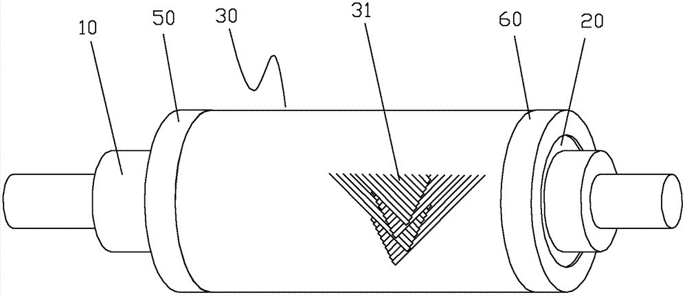
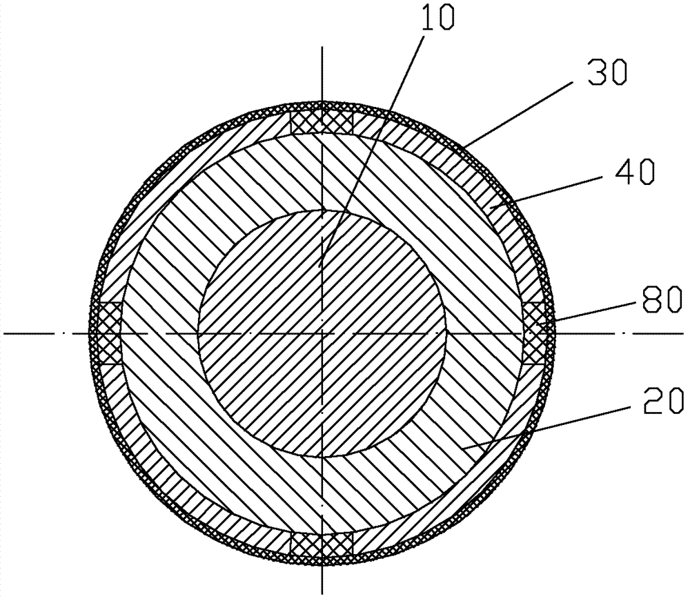
[0025] Such as Figure 1~2 As shown, according to the embodiment of the present invention, the motor includes a rotating shaft 10 , a rotor core 20 , a composite material layer 30 , a permanent magnet 40 , a protective cover 50 and a protective cover 60 , and an aluminum strip 80 .

[0026] The rotor core 20 made of silicon steel sheets is fixed on the outer surface of the motor shaft 10 and rotates together with the motor shaft 10 . The permanent magnet 40 covers the outer surface of the rotor core 20 , and the composite material layer 30 is arranged around the outer surface of the permanent magnet 40 . The protective sleeves 50 and 60 are fixed on both ends of the rotor core 20 and press th...


PUM

PropertyMeasurementUnit
widthaaaaaaaaaa

Abstract

The invention provides a motor permanent magnet fixing structure, a motor permanent magnet fixing method and a motor comprising the structure. The motor permanent magnet fixing structure comprises a rotor iron core, a permanent magnet and a composite material layer, wherein the permanent magnet is covered on the outer surface of the rotor iron core, and the composite material layer comprises expanding fiber bundles arranged around the outer surface of the permanent magnet. The fixing method comprises the steps of: step 1, sizing and expanding fiber bundles to form expanding fiber bundles; step 2, winding a plurality of expanding fiber bundles on the outer surface of the permanent magnet to form a fiber pre-forming body; and step 3, forming a composite material layer on the fiber pre-forming body by using a resin film infusion molding process. According to the motor permanent magnet fixing structure, the motor permanent magnet fixing method and the motor comprising the structure, the problem in the prior art that a gap between the permanent magnet and a stator winding is too large to cause magnetic flux leakage as the thickness of a protection layer for protecting the permanent magnet is too great can be solved.

Description

technical field [0001] The invention relates to the field of motors, in particular to a motor permanent magnet fixing structure, a fixing method and a motor including the structure. Background technique [0002] At present, high-speed motors are widely used in the field of commercial air conditioners. However, due to the poor reliability of the rotor permanent magnets and the low tensile strength of the permanent magnets, the centrifugal force on the permanent magnets must be limited within a certain range, and the motor speed cannot be exceeded. High, the outer diameter of the rotor can not be too large. This has caused the existing high-speed motors to be difficult to meet the increasingly higher motor speed requirements of commercial air conditioners. In order to overcome this difficulty, it is necessary to take effective protection measures for the permanent magnets to increase the firmness of the permanent magnets. [0003] There are two existing measures to protect t...

Claims


Application Information

Patent Timeline
Patent Type & Authority Applications(China)
IPC IPC(8): H02K1/28H02K15/03
Inventor 傅鹏张治平钟瑞兴蒋彩云蒋楠谢蓉闫秀兵
Owner GREE ELECTRIC APPLIANCES INC
Why Eureka
Try Eureka