Electrostatic impulse generator and direct current (DC) impulse generator

An electrostatic pulse and DC pulse technology, applied in the direction of friction generators, etc., can solve the problems of narrow applicability, large volume, and low output power density, and achieve the effects of convenient integration, broad application prospects, and simple structure

Active Publication Date: 2013-10-23
BEIJING INST OF NANOENERGY & NANOSYST
View PDF3 Cites 53 Cited by
  • Summary
  • Abstract
  • Description
  • Claims
  • Application Information

AI Technical Summary

Problems solved by technology

However, the electrostatic induction that has been invented has disadvantages such as large volume and narrow applicability, while electromagnetic induction generators and piezoelectric generators generally have defects such as complex structures, special requirements for materials, and high costs.
The electrostatic pulse generator that has been invented has a complex structure and low output power density, and has deficiencies in miniaturization, light weight, and integration, and cannot meet the needs of biomechanical energy collection such as human movement.

Method used


Image

  • Electrostatic impulse generator and direct current (DC) impulse generator
  • Electrostatic impulse generator and direct current (DC) impulse generator
  • Electrostatic impulse generator and direct current (DC) impulse generator

Examples


Embodiment 1

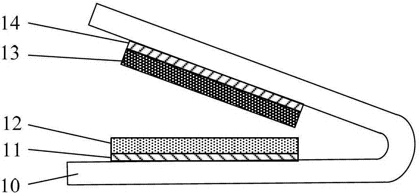
[0044] see figure 1 , the electrostatic pulse generator of this embodiment includes a flexible substrate 10 and a power generation unit, wherein: the flexible substrate 10 is a two-layer structure bent in a serpentine shape, and the two layers of substrates are connected to each other to form a V-shaped concave structure The power generation unit is arranged in the concave structure; the power generation unit includes: a first electrode layer 11 and a second electrode layer 14 arranged face to face on the inner surface of the concave structure (the inner surface of the flexible substrate 10); The first friction layer 12 disposed on the first electrode layer 11; contacting the second friction layer 13 disposed on the second electrode layer 14; the upper surface of the first friction layer 12 is arranged face to face with the upper surface of the second friction layer 13 , and the upper surface of the first friction layer 12 is separated from the upper surface of the second fric...

Embodiment 2

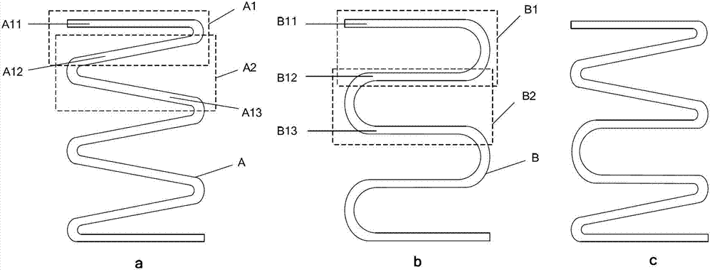
[0062] In this embodiment, the electrostatic nanogenerator includes a flexible substrate and a plurality of power generation units. For the flexible substrate, see image 3 , the flexible substrate is a serpentine bent laminated structure, the laminated structure has at least three layers, and any two adjacent layers are connected to each other to form a V-shaped or U-shaped concave structure. The number of V-shaped or U-shaped recessed structures included in the flexible substrate can vary depending on the situation. For details, see image 3 As shown in the middle figure a, the flexible substrate A is a serpentine bent laminated structure, and any two adjacent layers are connected to each other to form a V-shaped concave structure. In the figure, the A11-layer substrate is connected to the adjacent A12-layer substrate. Form a V-shaped concave structure A1 (shown in the dotted line box), the A12 layer substrate is connected to the adjacent A13 layer substrate to form a V-sha...

Embodiment 3

[0073] Taking the polyimide film material as the flexible substrate, the polytetrafluoroethylene film material as the first friction layer, and the aluminum metal (the second friction layer replaces the second electrode layer) material as the second friction layer to manufacture an electrostatic pulse generator as an example, The preparation process of the electrostatic pulse generator of this embodiment is specifically introduced.

[0074] see image 3, a polyimide film with a size of 4 cm × 4 cm × 125 microns is used as the substrate 101, and a 6-layer laminated structure is formed by folding to form 5 V-shaped concave structures. On the polytetrafluoroethylene film 103, an aluminum film with a thickness of 100 nanometers is prepared by electron beam evaporation as the first electrode layer 102, and the side of the aluminum film prepared from the polytetrafluoroethylene film faces the flexible substrate 101 and is fixed on the V-shaped concave structure. The inner surface. ...


PUM


Abstract

The invention provides an electrostatic impulse generator, which comprises a flexible base and power generation units, wherein any two adjacent layers of the base are mutually connected to form a V-shaped or U-shaped sunken structure, the power generation units are arranged in the sunken structures, the two layers on the inner surface of the V-shape or U-shape sunken structure respectively support a friction layer of the corresponding power generation unit, under the action of external force, the size of the opening of the V-shape or U-shape sunken structure of the flexible base is reduced to enable the two friction layers to be contacted with each other so as to generate surface charge transfer, when the external force disappears, the two friction layers of the power generation unit are separated from each other due to the rigidity of the flexible base, and pulse electrical signals are generated on electrode layers. Under the action of periodic external force, the two friction layers of the power generation unit are contacted with each other or separated from each other periodically by the drive of the flexible base, and the pulse electrical signals are generated between the two electrode layers of the power generation units.

Description

technical field [0001] The invention relates to the field of energy conversion, in particular to an electrostatic pulse generator and a DC pulse generator that convert naturally occurring mechanical energy such as motion, mechanical vibration, and fluid into electrical energy. Background technique [0002] Today, with the rapid development of highly integrated microelectronic devices, the research on the corresponding energy supply system is relatively lagging behind. In order to meet the needs of miniaturization, portability, and multi-function, the energy of these microelectronic devices comes directly or indirectly from traditional energy supply devices such as batteries. However, due to its own insurmountable limitations, including large volume and weight, limited service life, and potential harm to the environment and human body, it is difficult for batteries to meet the requirements of sustainability, low cost, and environmental protection. Therefore, it is of great s...

Claims


Application Information

Patent Timeline
Patent Type & Authority Applications(China)
IPC IPC(8): H02N1/04
Inventor 王中林白鹏朱光林宗宏
Owner BEIJING INST OF NANOENERGY & NANOSYST
Why Eureka
Try Eureka