Design method of LED (light-emitting diode) dimming driving switching power supply applied to various traditional dimmers

A dimmer, traditional technology, applied in the direction of light source, electric light source, electric lamp circuit layout, etc., can solve the problems of immature products, narrow dimming range, dimming flicker, etc., and achieve good dimming effect, high luminous efficiency, soft light effect

Inactive Publication Date: 2013-10-23
叶鸣
View PDF6 Cites 60 Cited by
  • Summary
  • Abstract
  • Description
  • Claims
  • Application Information

AI Technical Summary

Problems solved by technology

[0007] LED lighting technology is an emerging industry. In traditional incandescent lighting applications, many traditional dimmers have been widely used, but Because the traditional incandescent lamp has the disadvantage of high energy consumption, it has been phased out and needs to be replaced by LED lamps. Therefore, in this application field, LED needs to be redesigned to match the use of traditional dimmers. In the past technology , some people have tried research, but there are defects such as immature products, narrow dimming range, and dimming flickering, which cannot be practically used generally. The present invention is a research to solve such problems, and overcomes the past technical deficiencies

Method used


Image

  • Design method of LED (light-emitting diode) dimming driving switching power supply applied to various traditional dimmers
  • Design method of LED (light-emitting diode) dimming driving switching power supply applied to various traditional dimmers
  • Design method of LED (light-emitting diode) dimming driving switching power supply applied to various traditional dimmers

Examples


Embodiment Construction

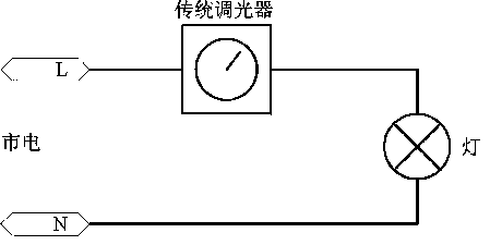
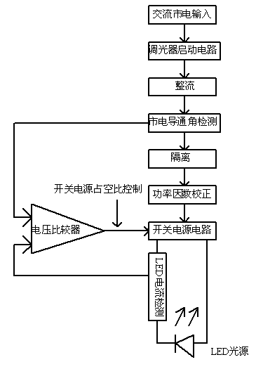
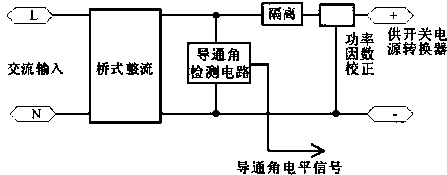
[0026] The specific embodiment of the present invention is: as figure 1 , figure 2 shown, figure 1 It is the wiring method of the dimmer and the power supply. The position where the light is connected is connected to the input end of the LED dimmable power supply. Silicon dimmer is a kind of leading edge modulation conduction angle phase size) the voltage after phase cut is added to the input terminals of the LED dimmable power supply, such as figure 2 , a small part forms a loop through the start-up circuit, which is used to start the conduction signal to the thyristor. The DC voltage signal is then compared with the voltage conversion signal on the LED current sampling resistor, and the compared value is fed back to the switching power converter, which determines the value of the working current on the LED, so that the conduction angle can be realized. To control the value of the current on the LED, so as to use the conduction angle of the traditional dimmer to control ...


PUM


Abstract

The invention provides a design method of an LED (light-emitting diode) dimming driving switching power supply applied to various traditional dimmers. According to the design method, the LED driving power supply achieves the resistive load input-output characteristics similar to those of an incandescent light bulb, so that LED lights (semiconductor LEDs) can be well suitable for dimming of the traditional dimmers (including traditional dimmers adjusting the phases of conduction angles through leading edge phase cut and traditional dimmers adjusting the phases of conduction angles through trailing edge phase cut, wherein silicon controlled dimmers are dimmers adjusting the phases of conduction angles through leading edge phase cut) and be used in indoor places where the traditional dimmers are needed for dimming. The LED dimming driving switching power supply designed according to the design method provided by the invention comprises a dimmer starting circuit loop, a rectifying circuit, a phase detection and isolation circuit, a phase cut detection circuit, a power-factor correction circuit, a switching power supply circuit and an LED current control circuit.

Description

[0001] technical field [0002] The invention relates to an LED dimming device suitable for traditional dimmers (leading-edge conduction angle adjustment and trailing-edge adjustment conduction angle, silicon-controlled silicon dimmer is a kind of leading-edge conduction angle adjustment) Background technique [0003] In the existing technology, traditional tungsten filament bulbs are used with traditional dimmers (leading-edge and trailing-edge adjustable conduction angles, thyristor dimmers are one type of leading-edge adjustable conduction angles) Brightness adjustment, the connection method is as follows figure 1 , the principle of the leading edge dimmer is that on the input voltage sine wave of each half cycle of the mains, the front part is not allowed to conduct, thereby reducing the effective value of the supply voltage to control the power of the lamp, that is, to control the brightness of the lamp. [0004] The principle of the trailing edge dimmer is that on th...

Claims


Application Information

Patent Timeline
Patent Type & Authority Applications(China)
IPC IPC(8): H05B37/02
Inventor 叶鸣
Owner 叶鸣
Why Eureka
Try Eureka