

Multifunctional machine vision device
A machine vision and multi-functional technology, which is applied in the direction of camera devices, lighting devices, lighting device components, etc., can solve the problems of small lighting range and uneven brightness, and achieve increased lighting range, uniform brightness, and human-machine functions. convenient effect
- Summary
- Abstract
- Description
- Claims
- Application Information
AI Technical Summary
Problems solved by technology
Method used
Image

Examples
Embodiment 1
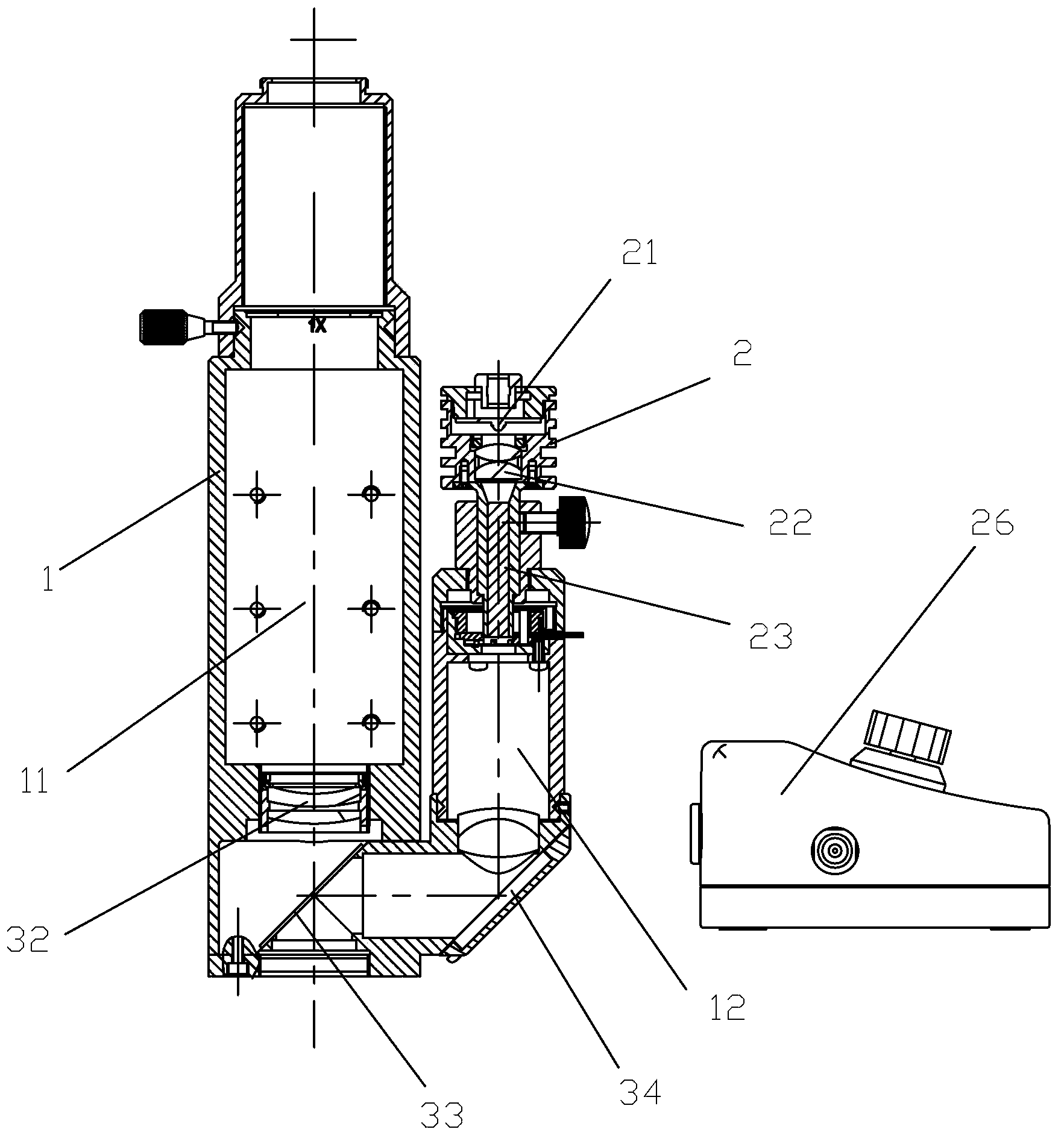
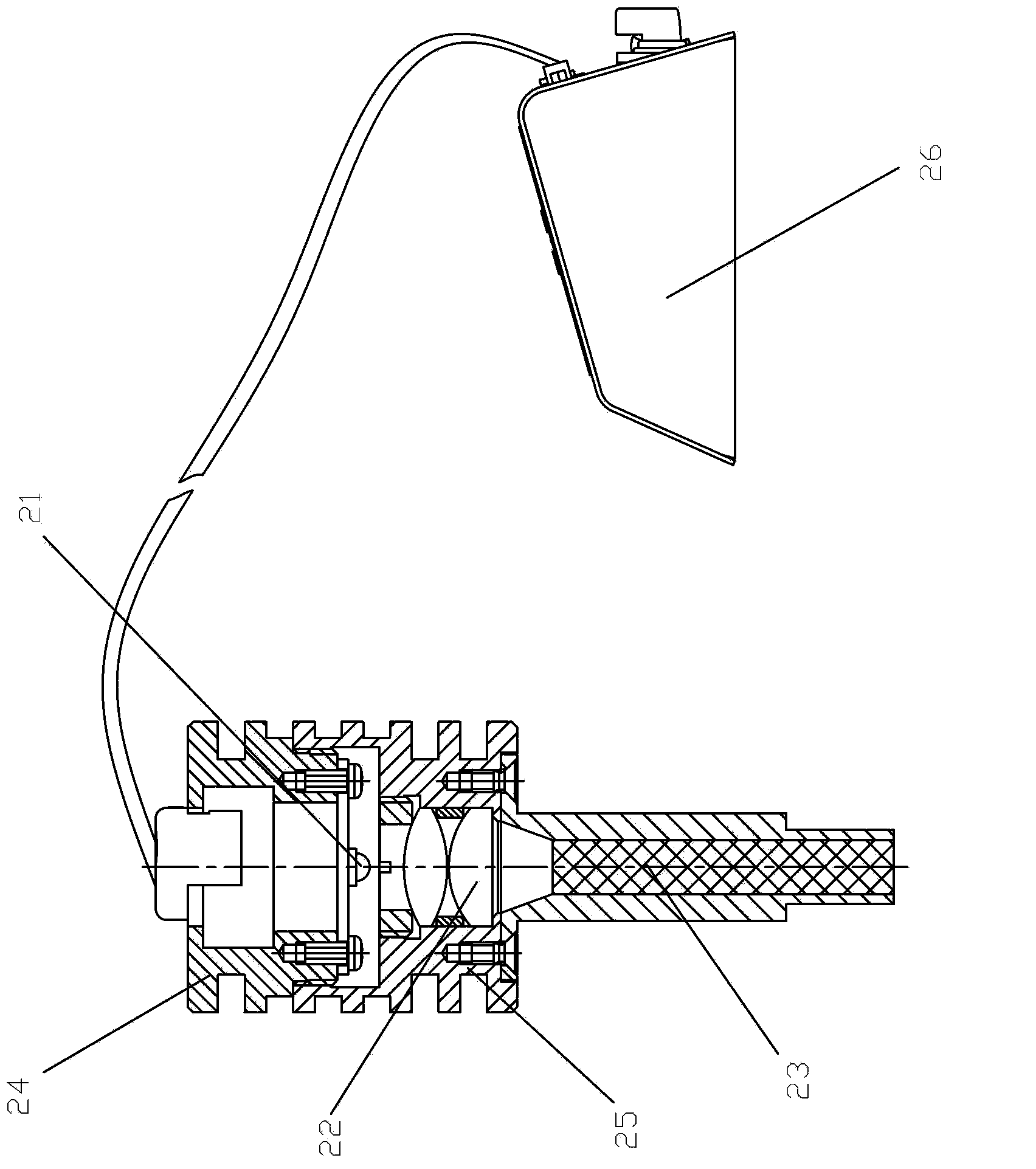
[0028] Embodiment one, see Figure 1 to Figure 3 As shown, a multifunctional machine vision device of the present invention includes a straight body assembly 1 and an LED fiber optic illuminator 2; the straight body assembly 1 has a main optical path channel 11 and an illumination optical path channel 12, and the bottom of the illumination optical path channel 12 is bent To the main optical path channel 11; the LED fiber optic illuminator 2 is installed on the upper end of the illumination optical path channel 12, and the LED fiber optic illuminator 2 includes an LED lamp 21, a condenser lens assembly 22 and an optical fiber 23 arranged in sequence from top to bottom, and the optical fiber 23 The upper end surface is arranged on the front focal plane of the LED lamp of the condenser lens assembly 22, so as to change the point light source into a surface light source.
[0029] The LED fiber optic illuminator 2 also includes an illuminator housing. The LED lamp 21 is fixed on th...
Embodiment 2
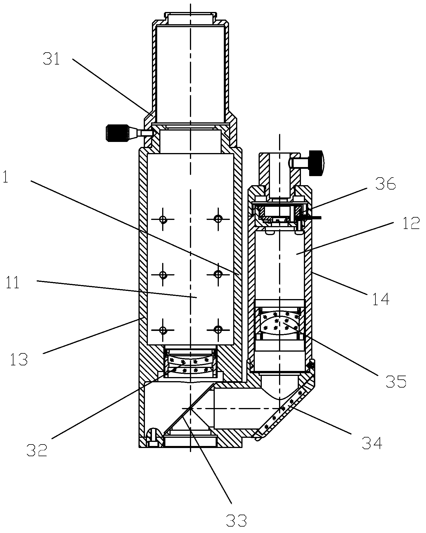
[0035]Embodiment two, see Figure 4 As shown, a multifunctional machine vision device of the present invention differs from Embodiment 1 in that the straight cylinder body assembly 1 further includes a third cylinder body 16 with a secondary optical path channel 15, a second mirror 37 and the second reflector 38; the secondary optical path channel 15 of the third cylindrical body 16 bends to the main optical path channel 11 of the first straight cylindrical body 13; In the first straight cylinder 13 of the main optical path; the second reflector 38 is installed in the secondary optical path 15 in the third cylinder 16, and its reflective surface faces both the secondary optical path and the illumination optical path.
Embodiment 3
[0036] Embodiment three, see Figure 5 As shown, a multifunctional machine vision device of the present invention is different from Embodiment 1 in that the straight barrel body assembly 1 further includes an autofocus device 4 and a third mirror 39, and the third lens The mirror 39 is obliquely arranged in the main optical path channel 11 at the bottom of the first straight cylinder 13 and is on the lower side of the first mirror 33, and the oblique direction is opposite to the first mirror 33; the autofocus device 4 is installed The bottom of the first straight cylinder 13.
PUM
 Abstract
Description
Claims
Application Information