
Strong-strength load bearing pallet

A high-strength, pallet-based technology, applied to rigid containers, containers, packaging, etc., can solve the problems of heavy weight and mechanical strength, and achieve the effect of large load-to-self-weight ratio, long stacking time, and convenient long-term storage

Inactive Publication Date: 2013-11-13
HEFEI GENIUS NEW MATERIALS
View PDF4 Cites 6 Cited by
  • Summary
  • Abstract
  • Description
  • Claims
  • Application Information

AI Technical Summary

Problems solved by technology

[0002] Ordinary plastic pallets have the advantages of light weight, waterproof, insect-proof, and moth-proof, but they need to be further improved in terms of their own weight, carrying weight and mechanical strength.

Method used


Image

  • Strong-strength load bearing pallet
  • Strong-strength load bearing pallet

Examples


Embodiment 1

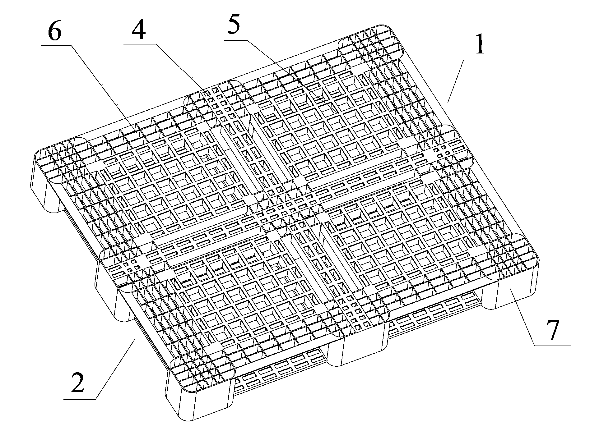
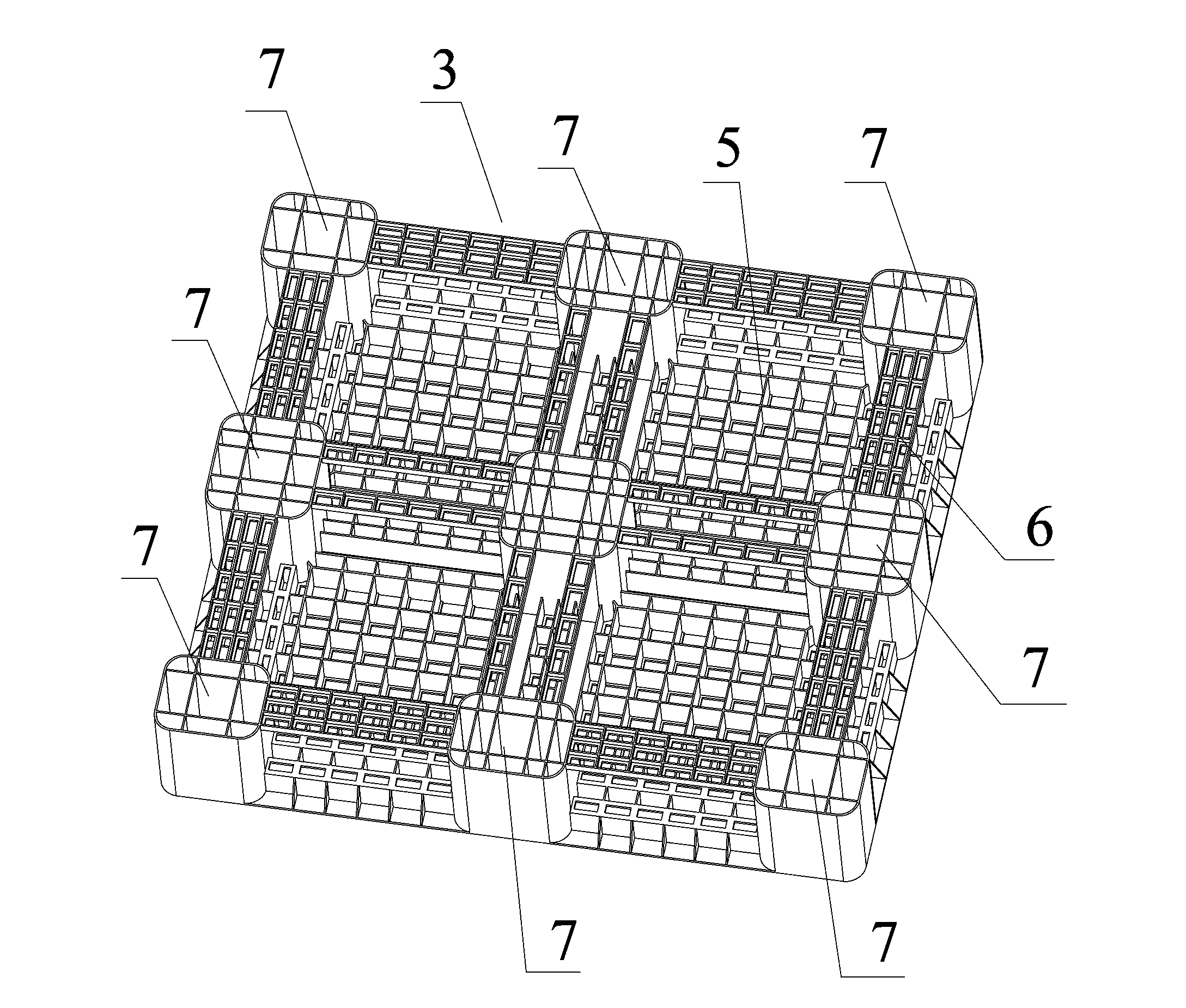
[0031] A high-strength load-bearing tray is injection molded from polypropylene PP and 30wt% glass fiber reinforced composite material, and its structure is as follows Figure 1-2 shown. The load-bearing tray is composed of an upper surface 1, a side surface 2 and a lower surface 3, wherein the upper surface 1 is composed of four horizontal grid-like structures, and between the grids is a hollow structure formed by grid ribs 4, and the grid ribs 4 are T-shaped structure, the upper end is the same width as the grid ribs, the height of the grid ribs 4 is 20mm, the width is 1.5mm, and the width of the hollow structure formed by the grid ribs 4 is 30mm.

[0032] A cross-shaped reinforcing rib 5 is arranged in the grid, and the width of the reinforcing rib 5 is 1.5 mm. The reinforcing rib 5 extends to the side 2 through the grid rib 4. The side 2 and the upper surface are connected at 90°, and the joint adopts a rounded corner transition, and the side is provided with a position ...

Embodiment 2

[0040] A high-strength load-bearing tray is injection molded from polypropylene PP and 45wt% glass fiber reinforced composite material, and its structure is as follows Figure 1-2 shown. The load-bearing tray is composed of an upper surface 1, a side surface 2 and a lower surface 3, wherein the upper surface 1 is composed of four horizontal grid-like structures, and between the grids is a hollow structure formed by grid ribs 4, and the grid ribs 4 are T-shaped structure, the upper end is 5 times the width of the grid ribs, the height of the grid ribs 4 is 50mm, the width is 5mm, and the width of the hollow structure formed by the grid ribs 4 is 70mm.

[0041] A cross-shaped reinforcing rib 5 is arranged in the grid, and the width of the reinforcing rib 5 is 5 mm. The reinforcing rib 5 extends to the side 2 through the grid rib 4. The side 2 and the upper surface are connected at 90°, and the joint adopts a rounded corner transition, and the side is provided with a position f...

Embodiment 3

[0048] A high-strength load-bearing pallet, the upper surface of which is composed of four horizontal diamond-shaped structures, and the rest of the structures are the same as in Example 1.


PUM


Abstract

The invention relates to a strong-strength load bearing pallet. The pallet is formed by injection-molding a composite thermoplastic material, and consists of an upper surface, lateral surfaces and a lower surface, wherein the upper surface consists of four horizontal squared structures; hollow structures consisting of grating ribs are arranged between the squared structures; cross-shaped reinforcing ribs are arranged in the squared structures; the lateral surfaces are connected with the upper surface at 90 degrees, and rounded corners are adopted for transition at joints; positions for a forklift truck are arranged on the lateral surfaces; every two lateral surfaces are connected at 90 degrees, and rounded corners are adopted for transition at joints; and the lower surface is provided with nine footings, one footing is arranged at a central position, and the other eight footings are uniformly distributed on the periphery of the lower surface, and are connected through connecting ribs. Compared with the prior art, the invention has the advantages that the pallet has the advantages of light weight, high load bearing capacity and longer service life; and during logistics transfer and production transportation, the pallet has remarkable advantages, and the cost can be remarkably reduced.

Description

technical field [0001] The invention relates to a plastic pallet, in particular to a high-strength load-bearing pallet. Background technique [0002] Ordinary plastic pallets have the advantages of light weight, waterproof, insect-proof, and moth-proof, but they need to be further improved in terms of their own weight, carrying weight and mechanical strength. [0003] The patented structure layout of the invention is reasonable, the processing technology is simple, the product weight is significantly lighter than that of the same kind of pallet, and the load capacity is large, which has obvious advantages in logistics turnover, production and transportation. It can not only reduce logistics costs, but also greatly increase the weight of transported goods and shorten the transport cycle. The development of plastic pallets is relatively fast. Most of the plastic pallets on the market are high in cost and heavy in weight. The present invention significantly reduces the weight ...

Claims


Application Information

Patent Timeline
Patent Type & Authority Applications(China)
IPC IPC(8): B65D19/24B65D19/40B65D19/38
Inventor 杨桂生王辉孙利明
Owner HEFEI GENIUS NEW MATERIALS
Learn More