Spiral-flow type heat pump dryer

A heat pump drying and swirling technology, which is used in drying solid materials, drying gas layout, drying, etc., can solve the problems of low ability to carry and control dust and harmful substances, low airflow velocity, uneven temperature distribution, etc. Achieve the effect of controlling and capturing dust and toxic and harmful substances, uniform temperature and speed distribution, and shortening drying time

Active Publication Date: 2013-11-20
江苏国莱特空调设备有限公司
View PDF9 Cites 12 Cited by
  • Summary
  • Abstract
  • Description
  • Claims
  • Application Information

AI Technical Summary

Problems solved by technology

In this way, there are problems such as uneven distribution of air temperature in the drying room, low air velocity and uneven distribution.
This will inevitably lead to unsatisfactory drying effect of the heat pump dryer
At the same time, due to the low air speed in the drying chamber, the heat and mass transfer efficiency between the air in the drying chamber and the material to be dried is low, resulting in a relatively long drying time, so the drying efficiency is low and the energy consumption is large
In addition, due to the uneven temperature distribution in the drying room, it will also affect the drying quality of the items.
If some dust and toxic and harmful substances will be produced during the drying process, due to the low air velocity in the drying room of the traditional heat pump dryer, the ability to carry and control dust and harmful substances is very low, and these dust and toxic and harmful substances will be deposited in the On the drying material and in the drying room, it is difficult to achieve effective capture and centralized treatment

Method used


Image

  • Spiral-flow type heat pump dryer
  • Spiral-flow type heat pump dryer
  • Spiral-flow type heat pump dryer

Examples


Embodiment Construction

[0027] The present invention will be further described in detail below in conjunction with the accompanying drawings and embodiments.

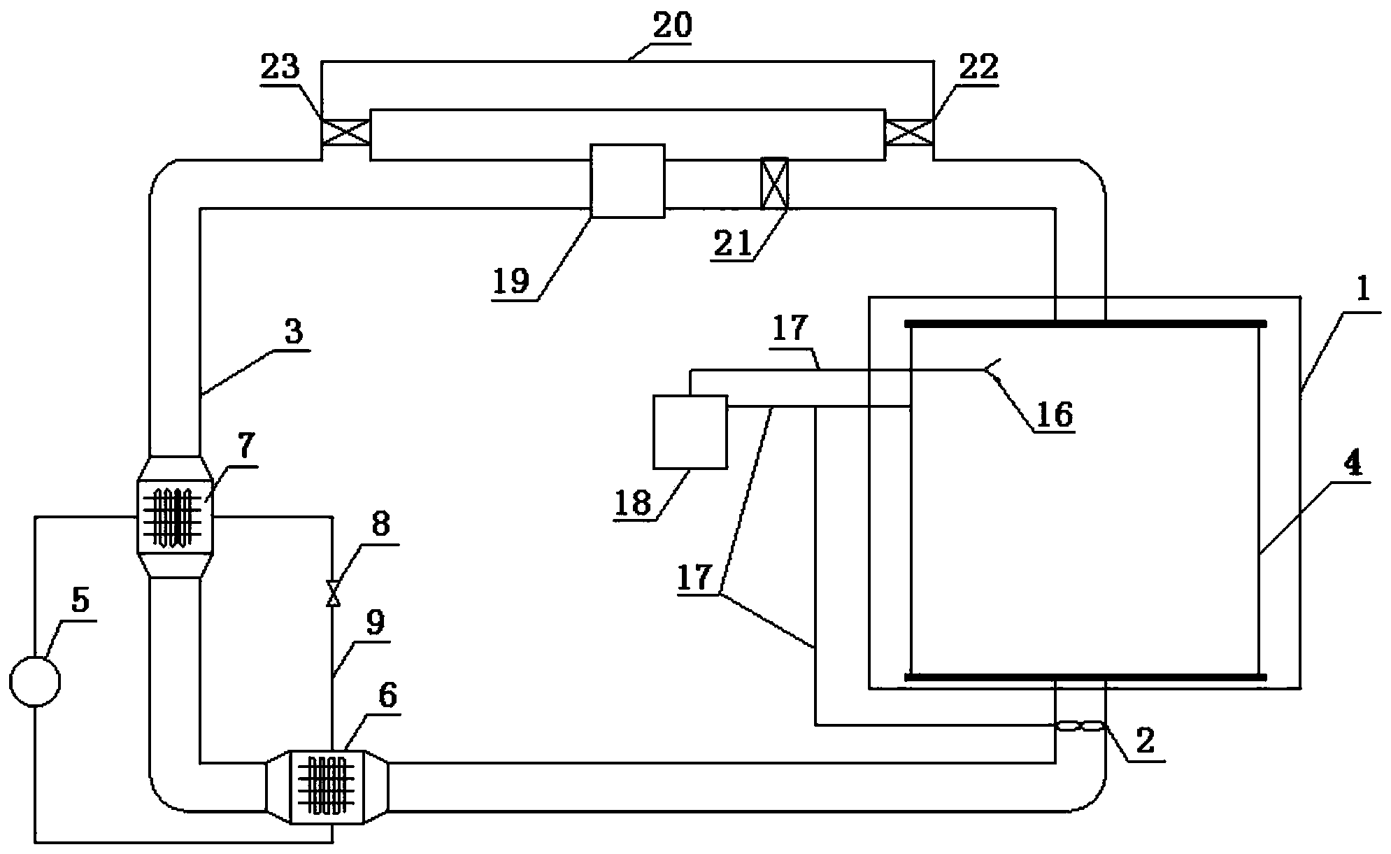
[0028] see figure 1 , this embodiment includes a heat pump system, a drying chamber 1 connected to the heat pump system, a frequency conversion fan 2 arranged at the air inlet of the drying chamber 1, and an air treatment passage 3 connecting the air outlet of the drying chamber 1 with the heat pump system; figure 1 It can be seen from the figure that the heat pump system includes a compressor 5, a condenser 6, an evaporator 7, a throttling device 8, and a refrigeration cycle channel 9 connecting various parts. The heat pump system is an existing mature technology and will not be described in detail here; The heat pump drying system is a closed drying system.

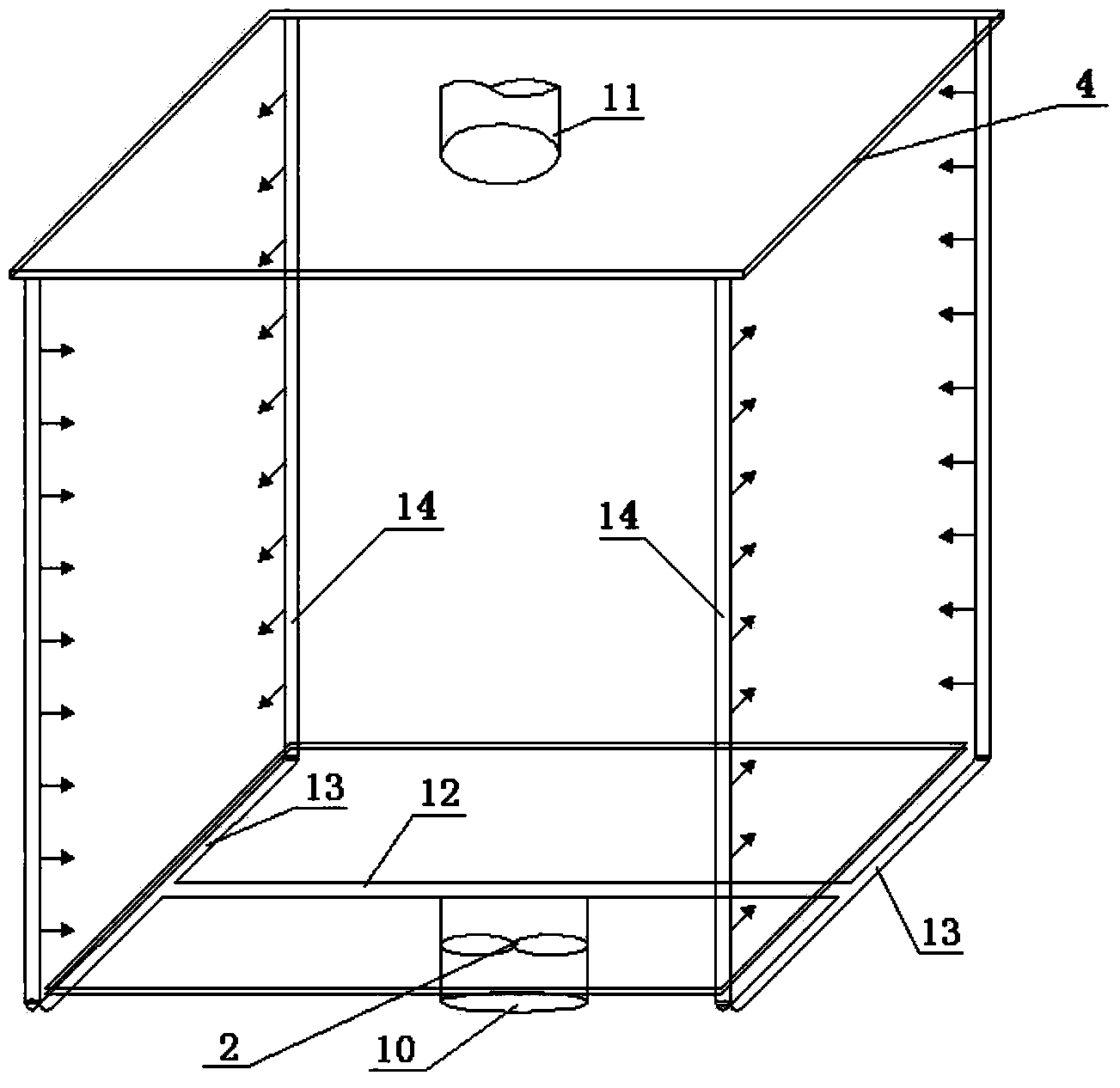
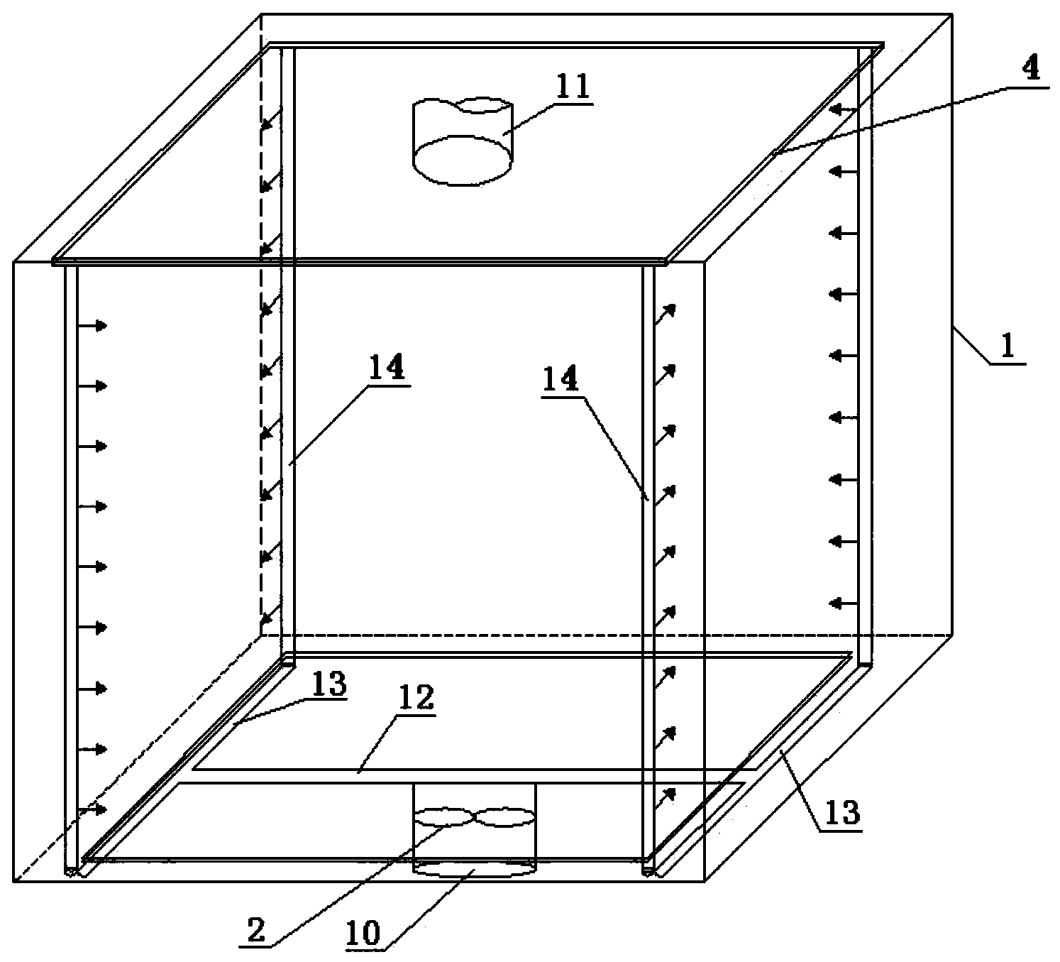
[0029] combine figure 2 , image 3 , a swirl generator 4 is provided in the drying chamber 1 (the swirl generator 4 and the drying chamber 1 can be integrated), the air inlet 10 at ...


PUM


Abstract

The invention belongs to the technical field of dryers, and particularly relates to a spiral-flow type heat pump dryer capable of being used in the fields of food processing, wood drying, cultural relic protection and the like. The spiral-flow type heat pump dryer is mainly characterized in that a spiral-flow generation device is arranged in a drying chamber; an air inlet of the drying chamber is formed in the bottom center of the drying chamber, and communicated with the bottom center of the spiral-flow generation device; an air outlet of the drying chamber is formed at the top center of the drying chamber; a control device is arranged, and comprises an inductor arranged in the drying chamber; the inductor is connected with a controller arranged outside the drying chamber by a signal transmission channel; and the controller is connected with the spiral-flow generation device and a frequency conversion fan by the signal transmission channel respectively. The spiral-flow type heat pump dryer can effectively improve air distribution in the drying chamber; an air flow can be distributed uniformly; an air speed in the drying chamber is increased greatly; and the drying efficiency and a drying effect of the heat pump dryer can be improved.

Description

technical field [0001] The invention belongs to the technical field of dryers, and in particular relates to a swirl heat pump dryer which can be used in the fields of food processing, wood drying, cultural relics protection and the like. Background technique [0002] Because the heat pump dryer can effectively recover and utilize the heat in the air, reduce the direct discharge of circulating air, and have obvious economic and social benefits in terms of energy saving and emission reduction, the application of heat pump dryers is becoming more and more extensive. However, the heat pump dryer still has the problem of low energy utilization efficiency. At present, the improvement of the drying effect of the heat pump dryer is mostly carried out from the transformation of the structural components of the system (such as: the structural optimization of the evaporator and condenser, the transformation of the air treatment channel, etc.), the selection of the heat pump cycle worki...

Claims


Application Information

Patent Timeline
Patent Type & Authority Applications(China)
IPC IPC(8): F26B21/00F26B25/00
Inventor 李永存夏国青高旭林爱晖王海桥邹声华王卫军刘荣华
Owner 江苏国莱特空调设备有限公司
Why Eureka
Try Eureka