Structured light visual sensor parameter calibration method for acquiring height information of welded joint

A visual sensor and parameter calibration technology, which is applied in the direction of optical devices, instruments, image data processing, etc., can solve problems such as complex methods, inability to guarantee parameter convergence, and slow speed

Active Publication Date: 2013-11-20
HEBEI UNIV OF TECH
View PDF7 Cites 27 Cited by
  • Summary
  • Abstract
  • Description
  • Claims
  • Application Information

AI Technical Summary

Problems solved by technology

This method needs to solve nonlinear equations with constraints, and introduces nonlinear optimization. The method is complicate

Method used


Image

  • Structured light visual sensor parameter calibration method for acquiring height information of welded joint
  • Structured light visual sensor parameter calibration method for acquiring height information of welded joint
  • Structured light visual sensor parameter calibration method for acquiring height information of welded joint

Examples


Embodiment 1

[0101] In this embodiment, the wedge-shaped target adopts a triangular wedge block with an acute angle of 30°, and the main equipment used is a camera, a laser, an encoder in the motion mechanism, a triangular wedge block with an acute angle of 30°, weldments, electronics, etc. Wedge-shaped vernier scale and servo motor, the camera mainly involves the camera lens;

[0102] The first step is to identify the horizontal deviation

[0103] By controlling the motor to move the camera along the parallel direction of the structured light belt for a distance of 10mm, and then calculating the pixel value of the welding seam moving in the up and down direction in the two-dimensional image, and then calculating the actual distance represented by each pixel, you can get The proportional coefficient K between the pixel value and the actual value, K=83;

[0104] The second step is to identify the vertical deviation

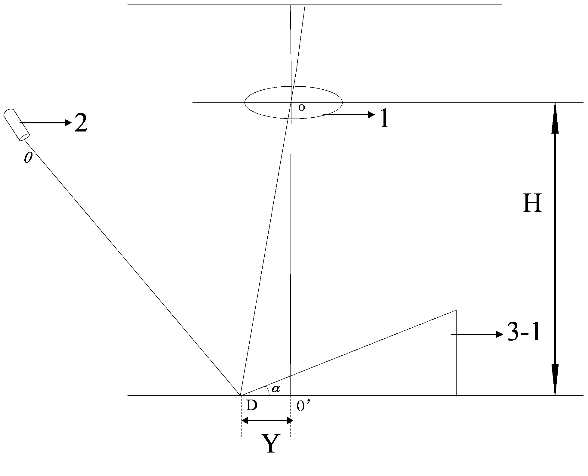
[0105] Step 2-I, operate as in the embodiment shown in Figure 1(b) above...

Embodiment 2

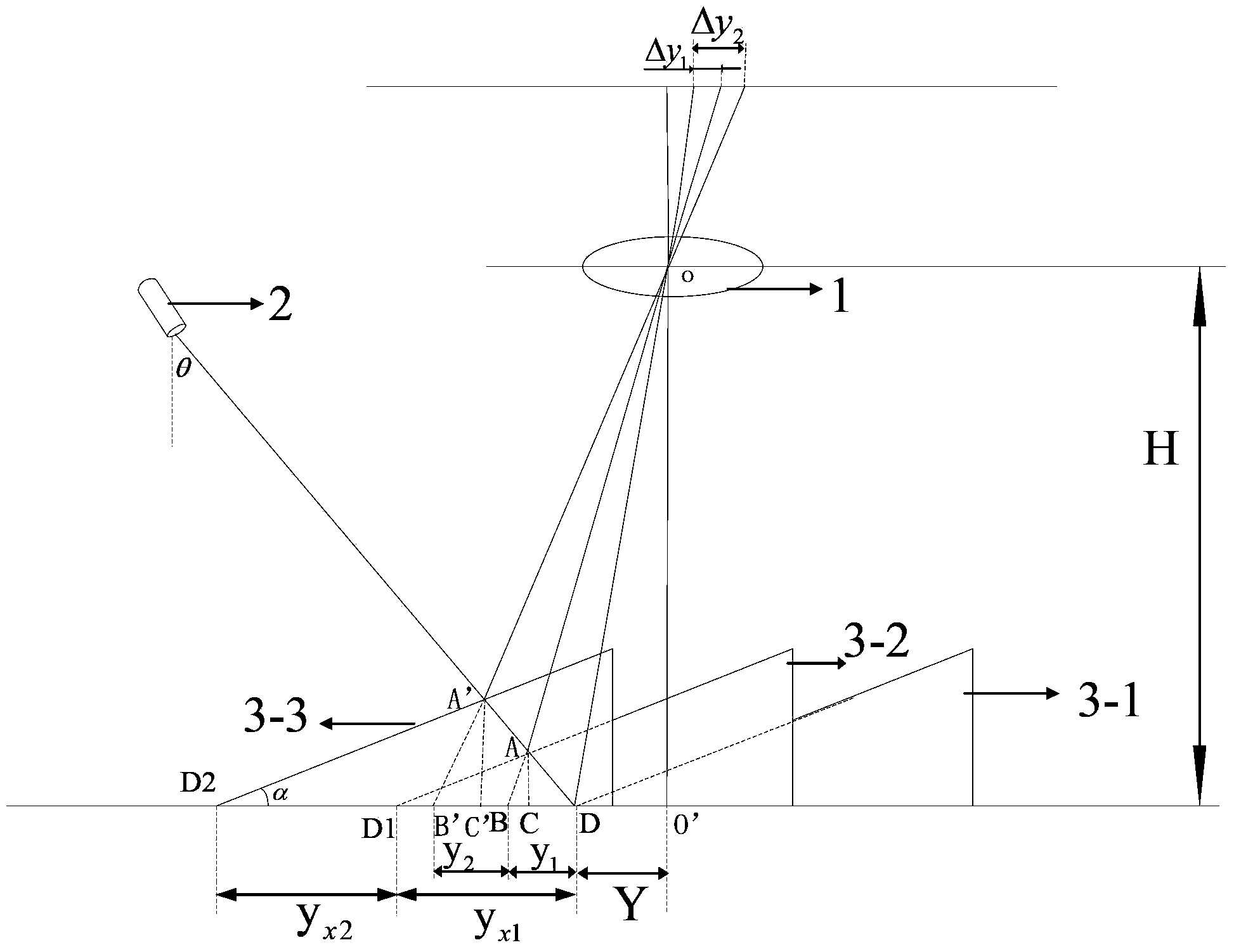
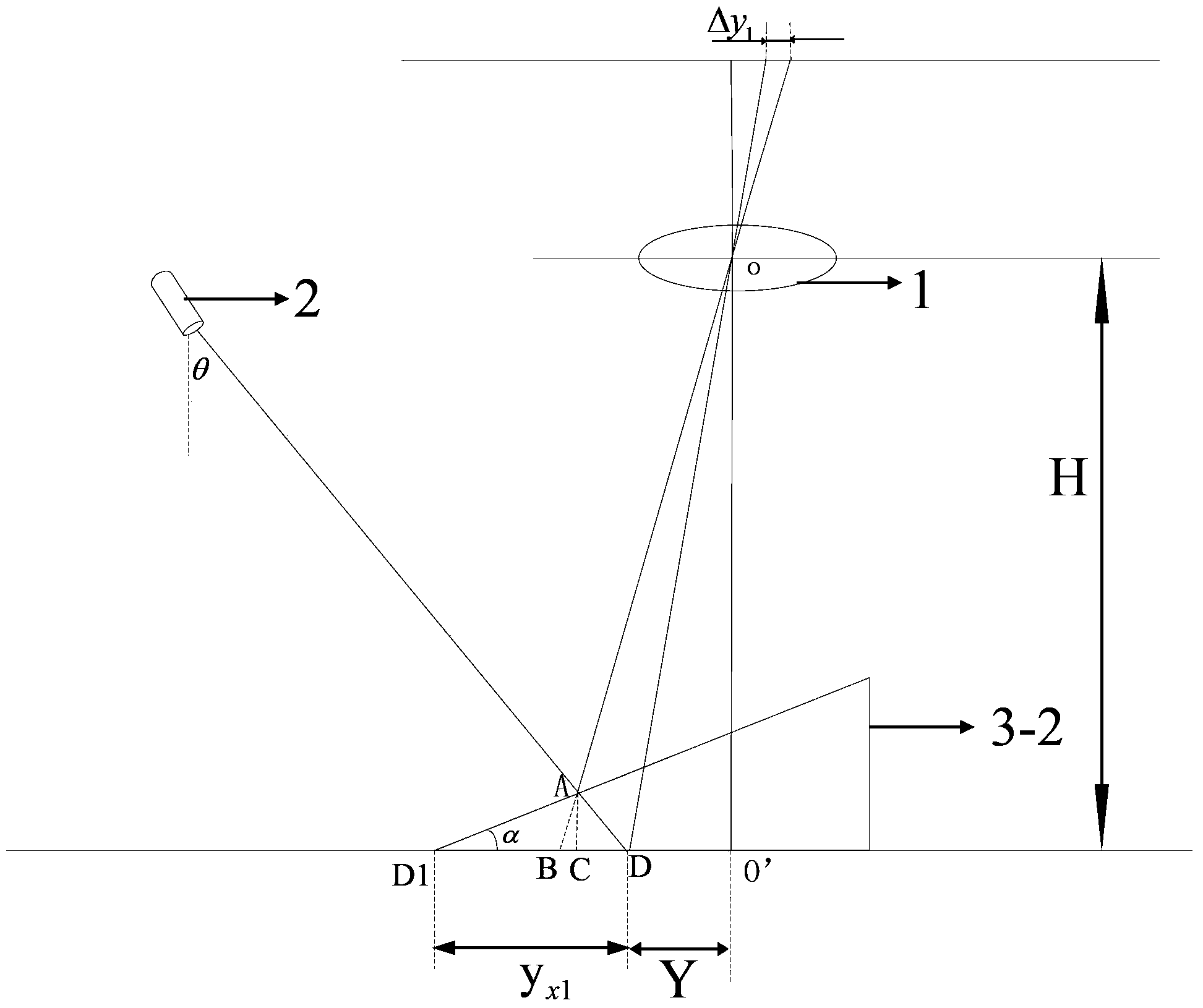
[0135] In addition to controlling the motor to move the camera along the vertical structured light direction, the triangular wedge moves forward to make the structured light belt rise above the horizontal plane h 1 = Stop at a height of AC=5mm, distance y x1 =10.079mm and the distance Δy that the structured light moves on the image plane 1 =0.01424mm; the triangular wedge moves forward to make the structured light belt rise to h above the horizontal plane 2 =A'C'=15mm stop height, distance y x2 =20.157mm and the distance Δy that the structured light moves on the image plane 2 =0.0325mm; In addition, other is the same as embodiment 1,

[0136] The camera calibration results are K=82.8, H=121.3, tanθ=0.2826, Y=-6.8612, where the negative sign does not represent the size, but only the direction information.

[0137] Move the weld along the vertical direction of the structured light until the structured light intersects the welding point where the height of the weld is to be m...

Embodiment 3

[0143] In addition to controlling the motor to move the camera along the direction parallel to the structured light strip by 15mm, the triangular wedge moves forward to make the structured light strip rise above the horizontal plane h 1 = AC = stop at a height of 15mm, distance y x1 =28.737mm and the distance Δy that the structured light moves on the image plane 1 =0.02594; The triangular wedge moves forward to make the structured light belt rise to h above the horizontal plane 2 =A'C'=25mm stop height, distance y x2 =21.443mm and the distance Δy that the structured light moves on the image plane 2 =0.05701mm; In addition, other with embodiment 1,

[0144] The camera calibration results are K=83.1, H=119.8, tanθ=0.2741, Y=-6.8856, where the negative sign does not represent the size, but only the direction information.

[0145] Move the weld along the vertical direction of the structured light until the structured light intersects the welding point where the height of the w...


PUM

PropertyMeasurementUnit
Acute angleaaaaaaaaaa

Abstract

The invention provides a structured light visual sensor parameter calibration method for acquiring height information of a welded joint, relates to the measurement non-specially applied to specific variable, and is a structured light visual system parameter calibration method based on a wedge-shaped target, which processes a two-dimensional image to obtain offset of structured light by calibrating obtained parameters so as to compute and obtain the height information of the welded joint and then to compute three-dimensional coordinate of an intersection point of a laser belt and the welded joint on the target, wherein the structured light visual sensor parameter calibration method specifically comprises the following steps of firstly recognizing horizontal deviation, secondly recognizing vertical deviation, thirdly calibrating structured light visual system parameters by utilizing a camera, and fourthly acquiring the height information of the welded joint. According to the structured light visual sensor parameter calibration method disclosed by the invention, the calibration process doest not involve a large-scale matrix transformation, the computation amount is smaller, a blockage problem of the target doest not exist, and the problem that the misconvergence of globally optimal solution generates in a solving process of a constrained nonlinear equation also does not exist.

Description

technical field [0001] The technical solution of the present invention relates to the measurement of non-specific variables, in particular, a method for calibrating parameters of a structured light vision sensor for obtaining weld height information. Background technique [0002] The calibration of the vision system is an important issue in robot vision. The image collected by the vision system, the one-to-one correspondence between the image coordinate position of each point and a certain point on the surface of the space object needs to be determined by the imaging model of the vision system, and the imaging model Each parameter of , needs to be determined through the calibration of the vision system, so the calibration of the vision system is the key to realize the conversion from 2D image information to 3D environment information. In the calibration process of the vision system, the acquisition of three-dimensional height information has always been a difficult problem. ...

Claims


Application Information

Patent Timeline
IPC IPC(8): G01B11/03G06T7/00G06T7/80
Inventor 陈海永孙鹤旭董砚杜晓琳崔丽娜
Owner HEBEI UNIV OF TECH
Why Eureka
Try Eureka