Rock and soil disintegration test device as well as using method

A test device and geotechnical technology, applied in the direction of soil material testing, measuring devices, material inspection products, etc., can solve the problems of very high precision requirements for measuring drainage devices, unsatisfactory processing of test results, and very high requirements for inner cylinder materials. Reduce the cost and complexity of the test, facilitate the promotion and use, and have the effect of simple structure

Inactive Publication Date: 2013-11-20
INST OF ROCK AND SOIL MECHANICS - CHINESE ACAD OF SCI
View PDF6 Cites 30 Cited by
  • Summary
  • Abstract
  • Description
  • Claims
  • Application Information

AI Technical Summary

Problems solved by technology

However, these methods generally have some disadvantages. For example, the first two test instruments and methods need to manually determine the stable state of the test submerged in water, and keep the buoy upright; the latter two methods have very high requirements on the material of the inner cylinder.
Moreover, thes

Method used


Image

  • Rock and soil disintegration test device as well as using method
  • Rock and soil disintegration test device as well as using method
  • Rock and soil disintegration test device as well as using method

Examples


Embodiment 1

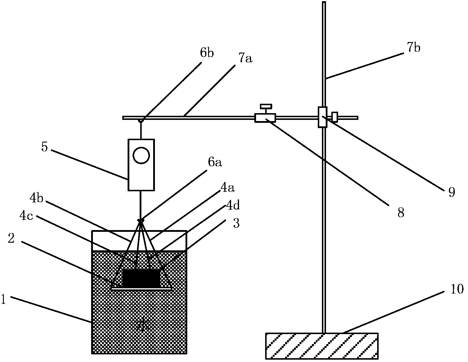
[0032] like figure 1 Shown is an engineering test device for determining the disintegration of rock and soil. The device includes: a support system, a data acquisition system, and a measurement system.

[0033] The support system as described includes: a second hook 6b, a first pole 7a, a second pole 7b, a horizontal telescopic valve 8, a vertical telescopic valve 9, and a base 10. It is characterized in that: the base 10 acts as a fixed support system, the base 10 is connected with the second pole 7b, the vertical expansion valve 9 is respectively connected with the second pole 7b and the first pole 7a, and the first pole 7a is equipped with a horizontal Telescopic valve 8. The height and position of the support system can be adjusted by adjusting the positions of the horizontal telescopic valve 8 and the vertical telescopic valve 9. The second hook 6b is suspended on the first pole 7a, and the bottom of the second hook 6b is connected with the spring dynamometer 5 .

[00...

Embodiment 2

[0037] A method for using an engineering test device for measuring rock and soil disintegration, the steps are:

[0038] A. Pour 1500ml of distilled water into the beaker 1, put the metal mesh 2 and the first copper wire 4a, the second copper wire 4b, the third copper wire 4c, and the fourth copper wire 4d into the distilled water in a no-load manner In the process, by adjusting the positions of the horizontal telescopic valve 8 and the vertical telescopic valve 9, the spring force gauge 5 is kept in a vertical state, so that the metal grid net 2 is located in the middle of the beaker 1, and the metal grid net 2 is in a suspended state. , record the reading F on the spring dynamometer 0 .

[0039] B. Use a ring knife with an inner diameter of 61.8mm and a height of 40mm to cut the soil sample, and push the soil sample out as the soil sample 3 to be tested; the rock sample 3 is prepared by a dry method with a cutting machine, with the same size of 61.8mm and a height of 40mm.

...


PUM


Abstract

The invention discloses a rock and soil disintegration test device as well as a using method. A base is connected with fulcrum bars; a vertical stretching valve is connected with the fulcrum bars respectively; a fulcrum bar is provided with a horizontal stretching valve, and a second hook is hung on the fulcrum bar; one end of a spring-loaded thrust meter is connected with the second hook; the lower part of the other end of the spring-loaded thrust meter is connected with the hook; copper wires are fastened to four edge corners of a metal grid net, and at the other end, the copper wires are twisted into a strand to be hung on the hook; rock and soil test samples are placed on the metal grid net, and then are immersed into a flask. The using method of the rock and soil disintegration test device comprises the following steps: (1) a no-load test, namely pouring distilled water into the flask, and recording the reading number F0 on the spring-loaded thrust meter; (2) rock and soil test sample manufacture, namely manufacturing a soil test sample and a rock test sample respectively by a cutting ring and a cutter; (3) a disintegration test, namely placing the rock and soil test samples on the metal grid net, and immersing into water, thus completing the test; (4) data processing. The rock and soil disintegration test device is simple in structure, easy to assemble and debug, low in cost, high in precision, good in stability and high in applicability, and can be widely applied to rock and soil engineering science research.

Description

technical field [0001] The invention relates to a rock and soil disintegration test device and a use method thereof, in particular to an engineering test device for measuring the disintegration of rock and soil, and also to a method for using the engineering test device for measuring the disintegration of rock and soil. Background technique [0002] The disintegration of rock and soil refers to the phenomenon that rock or soil is broken and scattered due to water immersion. The reason for the disintegration is that after the rock and soil body is submerged in water, the situation of water entering the pores or cracks is unbalanced, which causes the speed of the thickening of the intergranular diffusion layer to be unbalanced, so that the intergranular repulsion exceeds the suction force. Stress concentration is generated, and the rock and soil body collapses along the surface where the repulsive force exceeds the maximum suction force. At present, the research on the disint...

Claims


Application Information

Patent Timeline
IPC IPC(8): G01N33/24G01N5/00G01N15/02
Inventor 张先伟孔令伟雷美清
Owner INST OF ROCK AND SOIL MECHANICS - CHINESE ACAD OF SCI
Why Eureka
Try Eureka