

Light cutting device for optical chopper and controlling method thereof
A technology of optical chopper and controller, applied in the direction of optics, optical components, electrical program control, etc., can solve the problems of high-precision frequency output, small swing, low noise, etc., achieve fast start and stop speed, simple control, light weight effect
- Summary
- Abstract
- Description
- Claims
- Application Information
AI Technical Summary
Problems solved by technology
Method used
Image

Examples
Embodiment Construction
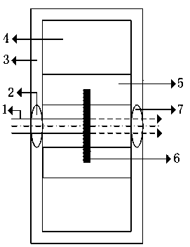
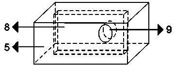
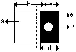
[0019] The present invention proposes a new method for modulating optical signals. In the new device, a metal light-shielding plate (conductor) is placed in a energized electromagnetic coil, and at the same time, the light-shielding plate is supplied with current, and the light-shielding plate The direction of the current flowing above is perpendicular to the direction of the magnetic field generated by the electromagnetic coil, so that the light baffle in the magnetic field will be subjected to electromagnetic force and move along the set chute under the action of this force. If the direction of the electric current flowing through the electromagnetic coil or the direction of the current flowing through the baffle is changed, the force direction of the light baffle is just opposite to the original direction, and under the new force, it will be transported in the opposite direction along the chute. The light hole is set so that the incident direction of the incident light is pe...
PUM
 Abstract
Description
Claims
Application Information