Parallel light curing equipment with staggered area array light sources and curing method thereof

A technology of dislocation arrangement and curing equipment, which is applied to the surface coating liquid device, pretreatment surface, coating, etc., which can solve the problem of low calorific value, UVLED luminous intensity, uniformity, and important indicators that are difficult to achieve actual results. And other problems, to improve the uniformity of irradiation, improve the effect of curing, improve the effect of optical power density and uniformity

Inactive Publication Date: 2013-11-27
广东科视光学技术股份有限公司
View PDF7 Cites 19 Cited by
  • Summary
  • Abstract
  • Description
  • Claims
  • Application Information

AI Technical Summary

Problems solved by technology

[0004] For equipment in various industries that currently use mercury lamps for curing, it is urgent to find alternative products for mercury lamps in the future to upgrade products, and the current use of UVLEDs is already a future development trend. UVLED replacement functions can reduce energy consumption. 80%, the service life is more than 20 times that of mercury lamps, and it has no pollution and low calorific value. Important indicators are still difficult to achieve the actual effect of mercury lamps, and it has become an industry problem to design high-performance UVLED optical systems to completely replace mercury lamps

Method used


Image

  • Parallel light curing equipment with staggered area array light sources and curing method thereof
  • Parallel light curing equipment with staggered area array light sources and curing method thereof
  • Parallel light curing equipment with staggered area array light sources and curing method thereof

Examples


Embodiment Construction

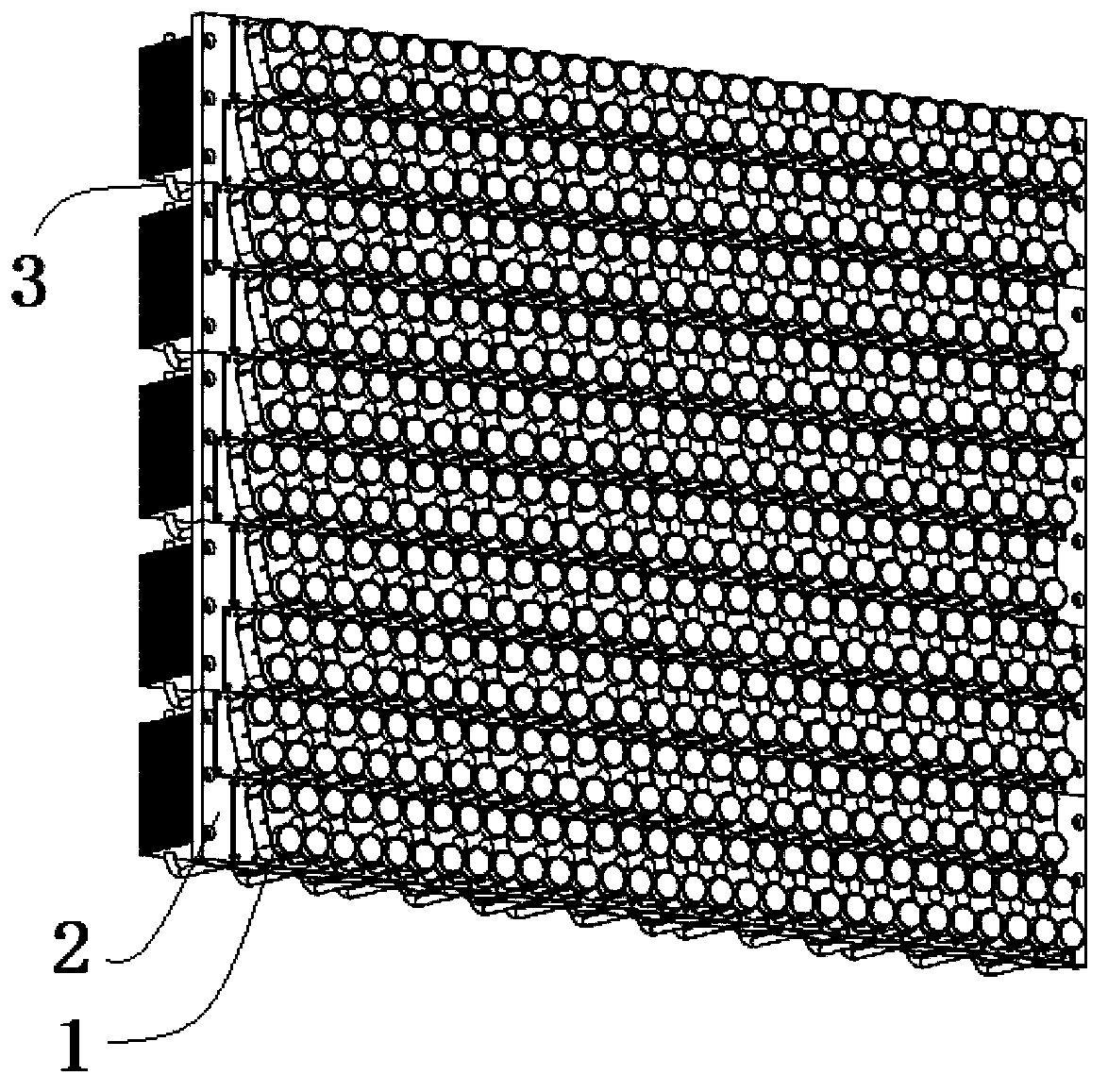
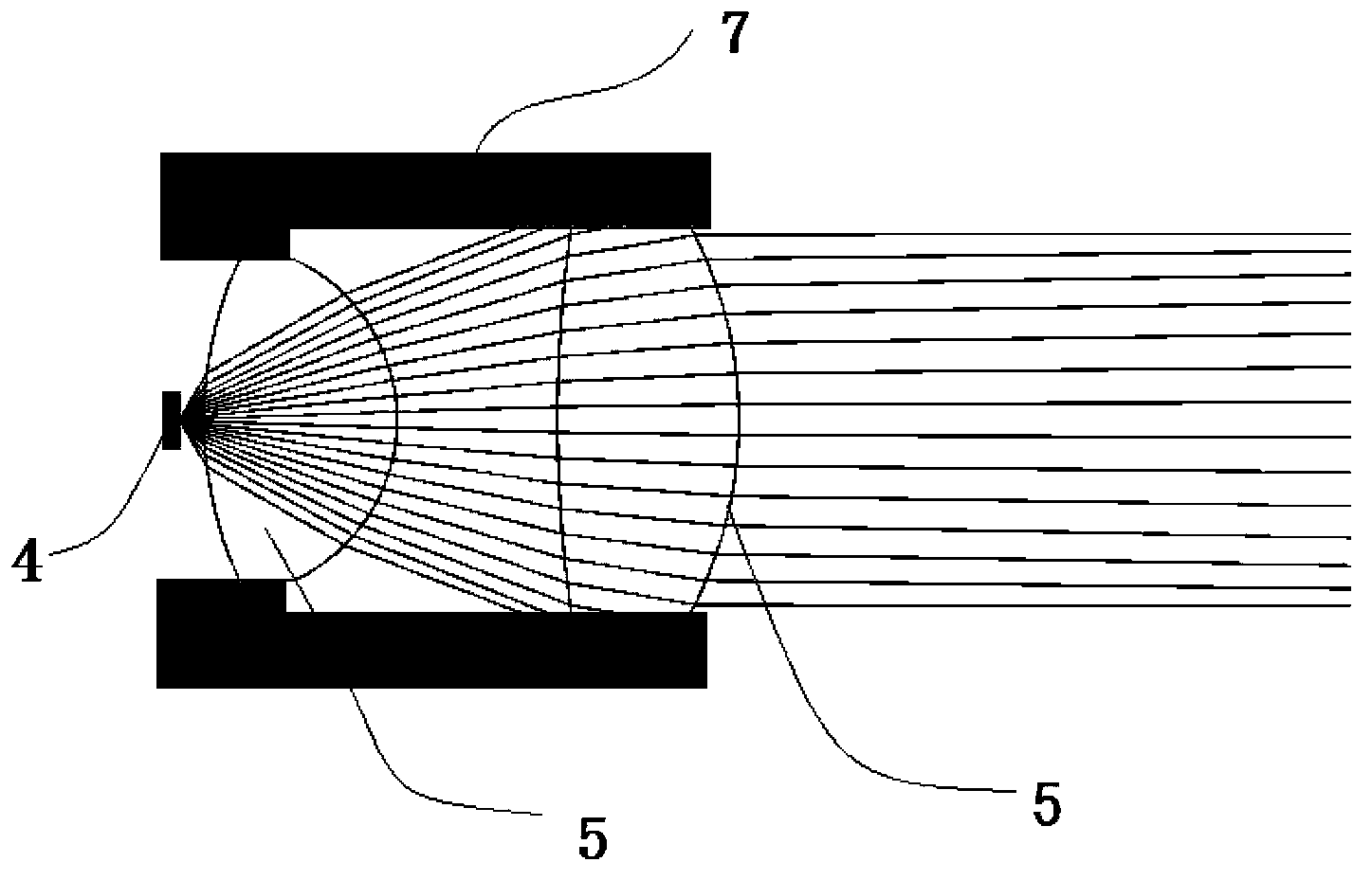
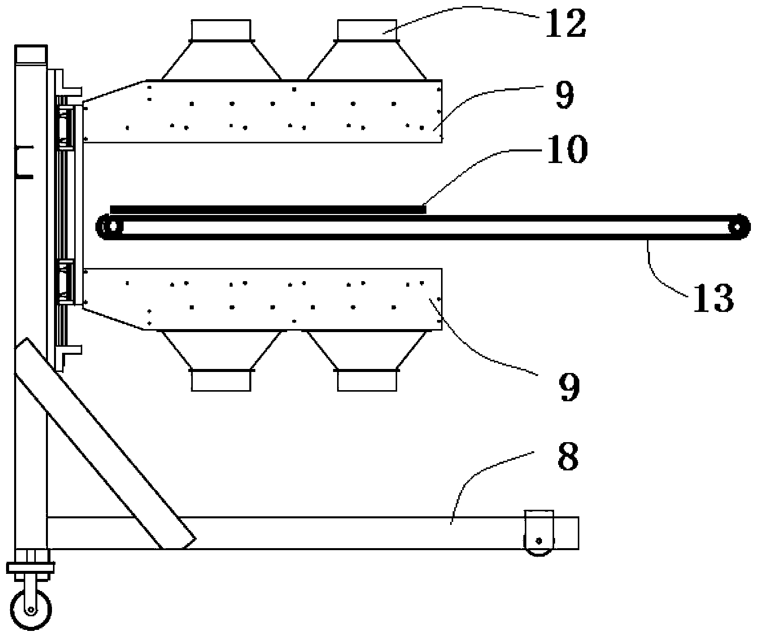
[0046] join Figure 1 to Figure 5 , the parallel photocuring equipment of the area array light source dislocation arrangement provided by the present invention, it comprises a conveying device 13, an area array light source curing device, a heat dissipation device connected with the area array light source curing device, a connection with the area array light source curing device The light source control device and the workbench for installing the above-mentioned devices; the workbench includes a trolley 8, which is movably arranged in the workbench, and the upper part of the trolley 8 is provided with a longitudinal guide rail and a guide rail drive mechanism, the area array light source curing device is arranged on the guide rail of the trolley 8; the conveying device 13 fixes a workpiece 10 to be cured by vacuuming, and transports the workpiece 10 to be cured to the area array light source curing device. directly above or directly below.

[0047] The area array light sourc...


PUM


Abstract

The invention discloses a piece of parallel light curing equipment with staggered area array light sources. The parallel light curing equipment comprises a conveying device, an area array light source curing device, a cooling device, a light source control device and a working table, wherein the cooling device is connected with the area array light source curing device, the light source control device is connected with the area array light source curing device, and the area array light source curing device is installed on the working table. The working table comprises a trolley. The trolley is movably arranged inside the working table. A longitudinal guiding rail and a guiding rail driving mechanism are arranged at the upper portion of the trolley. The area array light source curing device is arranged on the guiding rail of the trolley. The conveying device fixes a workpiece to be cured in a vacuumized mode and conveys the workpiece to be cured to the portion over the area array light source curing device or the portion under the area array light source curing device. The invention further discloses a curing method by utilizing the curing equipment. According to the parallel light curing equipment with the staggered area array light sources and the curing method, due to the fact that the staggered movements of the area array light sources and the workpiece are controlled, the evenness of curing is improved, and due to the fact that a condensing lens converts UV light beams into parallel light, the curing efficiency and precision are improved.

Description

technical field [0001] The present invention relates to parallel photocuring equipment and a curing method, in particular to a parallel photocuring device and a curing method in which an area array light source is misplaced and arranged in an ultraviolet curing technology, an optical technology, a motion control technology, and a light source control technology. Background technique [0002] In recent years, with the rapid development of industry, UV glue or UV ink is widely used as adhesive, solder mask and color ink in the fields of PCB circuit board curing, mobile phone touch screen curing, inkjet printing, ink printing and other fields in the electronics industry. etc. UV glue or UV ink needs to be irradiated by ultraviolet rays to be cured. At present, traditional curing equipment is usually cured by UV mercury lamps, which are characterized by high power consumption, short life, and generation of toxic gases. It has become an urgent need for industrial upgrading in the ...

Claims


Application Information

Patent Timeline
Patent Type & Authority Applications(China)
IPC IPC(8): B05D3/06
Inventor 王华叶建康邱冬冬邹波刘文刚袁雄建
Owner 广东科视光学技术股份有限公司
Why Eureka
Try Eureka