
Riveted plate for building installation and building installation structure

It is a technology for installation and riveting plates, which is applied in the direction of building components, building structures, buildings, etc. It can solve the problems of loose anchors, difficult work, and drooping gaps in connection holes, and achieves anti-loosening of connections, simple structure, The effect of making up for the deviation

Active Publication Date: 2015-12-09
浙江斯泰新材料科技股份有限公司
View PDF5 Cites 0 Cited by
  • Summary
  • Abstract
  • Description
  • Claims
  • Application Information

AI Technical Summary

Problems solved by technology

[0002] At present, the anchor bolts used in the installation of building auxiliary structures, due to the impact of hundreds of thousands of wind wave external force or the braking shock vibration during subway operation, will cause the anchors to loosen and the gap between the connecting holes to sag, resulting in accidents.
Therefore, in order to prevent the bolts from loosening and the gap between the connecting holes from sagging, the national regulations require that the screw, gasket, nut and the connecting anchor plate be welded to death. However, this welding on the construction site is not only difficult, but also exists Potential safety hazards of desoldering caused by welding on several different materials

Method used


Image

  • Riveted plate for building installation and building installation structure
  • Riveted plate for building installation and building installation structure
  • Riveted plate for building installation and building installation structure

Examples


Embodiment Construction

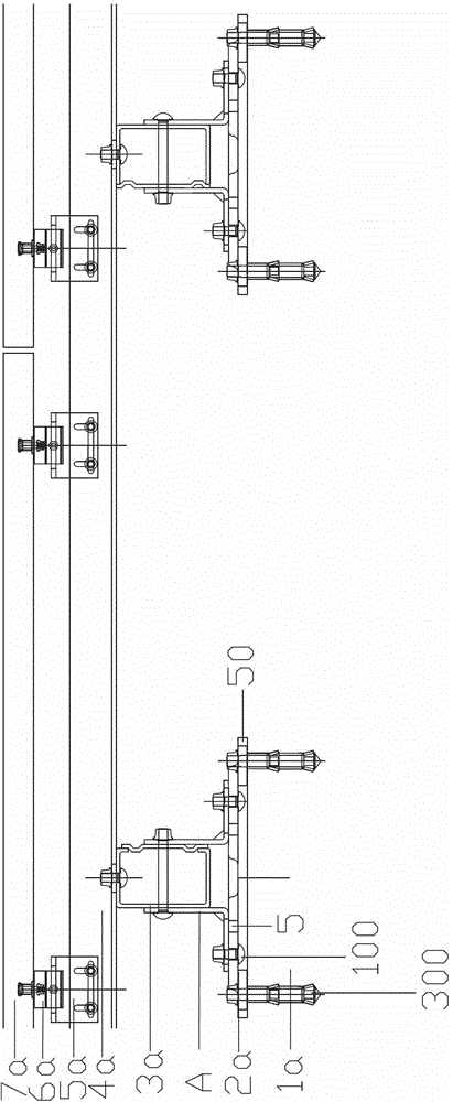
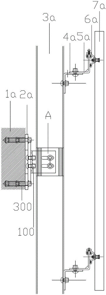
[0066] Such as figure 1 , 1a In the curtain wall installation system shown, the labels of each component are: 1a, concrete foundation, 2a, riveted plate connected with the concrete foundation, A, secondary connector of the present invention, 3a, hollow column, 4a, beam, 5a, Hook receiving seat, 6a, hook, 7a, curtain wall panel.

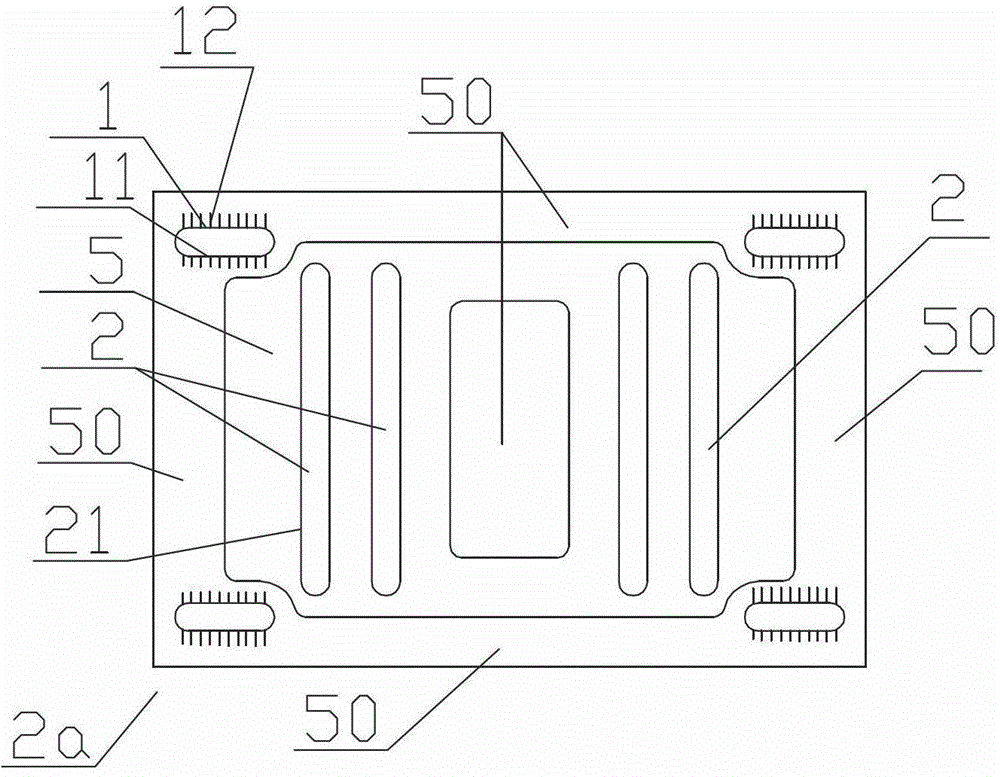
[0067] The riveted plate 2a for building installation provided by the present invention comprises a first connecting hole 1 for installing the riveted plate itself and a second connecting hole 2 for installing the next-level connecting structure; the first connecting hole 1 and the second The two connection holes 2 are long holes, and their length directions are vertical, such as figure 2 with Figure 2c As shown, that is, if the first connection hole 1 is a horizontal long hole, the second connection hole 2 is a vertical long hole, and vice versa.

[0068] The rivet plate has a bottom area 50 and an upwardly arched portion 5, the bottom area 50 ...


PUM


Abstract

The invention provides a rivet plate for construction installation and a construction installation structure. The rivet plate comprises first connecting holes and second connecting holes; the length directions of the first connecting holes are perpendicular to those of the second connecting holes; the first connecting holes and the second connecting holes are slot holes; the rivet plate is provided with a bottom area and an upwardly arched portion, the first connecting holes are positioned in the bottom area, and the second connecting holes are positioned on the arched portion; a circle of inner teeth is arranged on the wall of each of the first connecting holes and the second connecting holes; concave-convex positioning structures are arranged in the bottom area of the front surface of the rivet plate and are located at compressed positions, which correspond to fasteners, of the peripheral surfaces of orifices of the first connecting holes; concave-convex positioning structures are arranged on the arched portion of the back surface of the rivet plate and are located at compressed positions, which correspond to fasteners, of the peripheral surfaces of orifices of the second connecting holes. The rivet plate and the construction installation structure have the advantages that installation and connection positions can be adjusted, deviation due to errors or position adjustment in a construction installation system can be offset, the rivet plate can have position relations with the fasteners and can be tightly connected with the fasteners, welding operation is omitted while looseness of connection among the rivet plate and the fasteners is prevented, and seismic requirements can be met. The invention further provides a fire prevention and heat resisting solution for the connection structure.

Description

technical field [0001] The invention relates to a riveted plate for building installation and a building installation structure. It is mainly suitable for construction of various buildings, subways, etc., and is more suitable for the use of curtain walls of building envelopes with high requirements for anti-vibration and fire protection. Background technique [0002] At present, the anchor bolts used in the installation of building auxiliary structures are affected by hundreds of thousands of wind wave external forces or braking shock vibrations during subway operation, which will cause the anchors to loosen and the gap between the connecting holes to sag, resulting in accidents. Therefore, in order to prevent the bolts from loosening and the gap between the connecting holes from sagging, the national regulations require that the screw, gasket, nut and the connecting anchor plate be welded to death. However, this welding on the construction site is not only difficult, but al...

Claims


Application Information

Patent Timeline
IPC IPC(8): E04B2/88E04B1/94E04B1/98E04F13/23
Inventor 张清华徐洁媛徐跃华张建奇陈丽娟朱艺章蓓杜奕奎
Owner 浙江斯泰新材料科技股份有限公司
Learn More