MWD (monitoring while drilling) device and method for vibration of down-hole drill string

A monitoring device and drill string technology, applied in surveying, earthwork drilling, wellbore/well components, etc., can solve problems such as damage to ground equipment, increased drill string wear, and working effectiveness of drilling tools

Active Publication Date: 2013-11-27
SOUTHWEST PETROLEUM UNIV
View PDF7 Cites 17 Cited by
  • Summary
  • Abstract
  • Description
  • Claims
  • Application Information

AI Technical Summary

Problems solved by technology

[0003] The longitudinal vibration of the drill string is carried out on the axis of the drill string. Its vibration is like the movement of heavy objects suspended at the lower end of the spring. It is mainly caused by the teeth alternately contacting the bottom of the well. It is different from the structure of the drill bit, the nature of the formation, and the pump volume. It is related to factors such as uniformity, WOB and rotational speed. When the longitudinal vibration is severe, the drill string will produce alternating tensile and compressive stress near the neutral point, which will easily lead to fatigue fracture failure of the drill string at the neutral point, and may also cause damage to the drill bit and damage to the drill string. Increased column wear and damage to ground equipment; drill string lateral vibration (also known as string vibration) vibrates like a string in a certain part of the drill string, mainly due to the centrifugal force and the drill string during the rotation of the drill string. Caused by the collision with the well wall, especially when the drill string is bent by the wellbore, it will intensify the yaw, and the lateral vibration often causes the drill string to bear the alternating stress at the bend, resulting in the fatigue fracture of the drilling tool; the drill string torsional vibration (also known as Spring shimmy) like the spring in the clock drives the balance wheel to twist repeatedly, mainly due to the intermittent-stick-slip motion of the bottom hole, the intermittent-stick-slip motion is mainly due to the dry friction between the bottom hole assembly and the rock As a result, the torsional movement will intensify the reversal of the drill string, generate alternating shear stress, and shorten the service life of the drill string
[0004] Drill string longitudinal, lateral, torsional vibration and its coupling vibration can easily lead to the actual performance of drilling tools such as drill string, drilling tools, and drill bits, thereby inducing major drilling accidents such as drill string fracture
For this reason, many scholars have analyzed the dynamic characteristics of the drill string through the drilling tool dynamics analysis method, trying to use theoretical analysis to analyze the drill string vibration, in order to seek solutions to prevent drilling tool failure, scientifically control wellbore trajectory, improve drilling efficiency, and reduce drilling costs. However, due to the complex interaction between the downhole drill string, the well wall and the bottom hole, it is difficult to obtain accurate results through theoretical methods, and direct measurement is the most direct way to accurately obtain drill string vibration parameters or data
[0005] At present, the methods of measuring drill string vibration at home and abroad can be divided into surface measurement method and downhole measurement while drilling method. The surface measurement method is mainly to install a triaxial acceleration sensor at the tap to measure the triaxial The vibration data is the result of the vibration of the downhole drill string being transmitted to the ground through the drilling tool. The vibration data obtained by this ground measurement is not real enough, and the collected signal has obvious attenuation, and it is accompanied by a large number of noise signals, especially In the case of well drilling with complex structures such as inclined wells, horizontal wells, extended-reach wells, and three-dimensional trajectory wells, the vibration data measured on the surface of the wellhead (or near the wellhead) basically loses its authenticity and practicability, and can only be used as an aid for decision-making The reference basis cannot be used as the most important basis for decision-making; the downhole measurement while drilling method is mainly to install a triaxial acceleration sensor near the drill bit to detect the vibration acceleration of the drill string, and the measured vibration data can be transmitted through wired transmission, mud pulse or ultrasonic waves. to the surface, it can also be stored in the downhole memory, and played back after the drill is pulled out. The data directly measured downhole, because it is near the drill bit, has higher accuracy than ground measurement and can more truly reflect the position near the drill bit. Actual vibration
At present, the schemes of devices or instruments for measuring downhole drill string vibration at home and abroad mainly use triaxial acceleration sensors (borehole Cartesian coordinates X / Y / Z axis) to measure drill string vibration acceleration, and the acceleration measured by triaxial acceleration sensors The signal can not monitor the lateral vibration and the torsional vibration parameters under the drill string vibration situation respectively, therefore, it is necessary to design the downhole drill string vibration monitoring device and method that can respectively measure the drill string longitudinal vibration, lateral vibration and torsional vibration parameters , so that technicians can better grasp the actual working conditions of the downhole drill string and drill bit

Method used


Image

  • MWD (monitoring while drilling) device and method for vibration of down-hole drill string
  • MWD (monitoring while drilling) device and method for vibration of down-hole drill string
  • MWD (monitoring while drilling) device and method for vibration of down-hole drill string

Examples


Embodiment Construction

[0050] The present invention will be further described below in conjunction with accompanying drawing, protection scope of the present invention is not limited to the following:

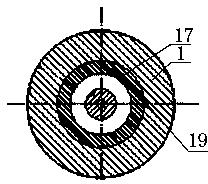
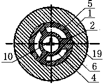
[0051] like Figure 1 to Figure 6 As shown, a downhole drill string vibration monitoring device while drilling, which includes a drill collar sub-section 1, the upper and lower ends of the drill collar sub-section 1 connecting thread is designed as NC50 digital thread, so that the drill collar sub-section 1 can be combined with the lower drilling tool The inner wall of the drill collar nipple 1 is stepped, and the inner diameter of the inner wall of the upper section of the drill collar nipple 1 is larger than the inner diameter of the inner wall of the lower section, and the inner wall of the upper section of the drill collar nipple 1 is provided with an upper protective joint 2 and the lower protection joint 3, the upper protection joint 2 and the lower protection joint 3 are all double-layer casin...


PUM


Abstract

The invention discloses an MWD device for vibration of a down-hole drill string. The device comprises a drill collar short section (1), wherein an upper protection joint (2) and a lower protection joint (3) are arranged in the drill collar short section (1); an acceleration sensor (10) is arranged in an accommodating cavity (8) formed by the upper protection joint (2) and the lower protection joint (3); the lower end of the lower protection joint (3) is connected with a detection pipe (12); a battery pack (15) and an electronic circuit board (16) are fixedly arranged in the detection pipe (12); and the electronic circuit board (16) is connected with the battery pack (15) and the acceleration sensor (10). The invention further discloses a monitoring method. The MWD device and method for the vibration of the down-hole drill string have the benefits as follows: the problem that a conventional device cannot detect longitudinal vibration, lateral vibration and torsional vibration of the drill string respectively is solved, the measurement is accurate, and information distortion is avoided; and the device can be mounted at different parts of the drill string and can be connected with an MWD device for usage, abnormal vibration can be transmitted to the ground in real time, the structure is simple, the work is reliable, and the service life is long.

Description

technical field [0001] The invention relates to the technical field of downhole drilling tool vibration monitoring during oil and gas drilling, in particular to a downhole drill string vibration monitoring device and method while drilling. Background technique [0002] As the exploration and development of my country's oil and gas resources continue to deepen, it has developed from conventional oil reservoirs to hidden oil reservoirs and complex oil reservoirs, from shallow to deep, and from east to west and ocean. The drilling environment has become increasingly harsh and the difficulty of drilling has been increasing Large, new drilling technologies and techniques (wells with complex structures, wells with special techniques, deep wells and ultra-deep wells, wells with slim holes, etc.) are emerging and widely adopted, and complex and harsh working conditions, as well as new drilling techniques and techniques, mostly bring new challenges. Drill string vibration also brings n...

Claims


Application Information

Patent Timeline
Patent Type & Authority Applications(China)
IPC IPC(8): E21B47/00
Inventor 马天寿陈平
Owner SOUTHWEST PETROLEUM UNIV
Why Eureka
Try Eureka