Through hole spring and helical blade rotor in heat exchange tube

A technology of spiral blades and heat exchange tubes, which is applied in the direction of heat exchanger shells, rotating equipment cleaning, heat exchange equipment, etc., can solve problems such as damage to the inner wall of heat exchange tubes, multi-fluid kinetic energy, and fast rotor rotation speed, and achieve improved damage function, enhance the effect of turbulence, and reduce the effect of contact area

Active Publication Date: 2013-11-27
BEIJING UNIV OF CHEM TECH
View PDF8 Cites 2 Cited by
  • Summary
  • Abstract
  • Description
  • Claims
  • Application Information

AI Technical Summary

Problems solved by technology

In general, the spiral bond has the following main disadvantages: (1) The bond is a whole, which directly scratches the heat transfer tube and damages the inner wall of the heat transfer tube; (2) When the fluid flows to push the bond to rotate, it requires a large driving torque and consumes more (3) The service life of the bearing used for single-end fixing is short; (4) The effect of field synergy enhanced heat transfer generated by the bond is not significant
But the disadvantage is that when a certain fluid passes through, the rotation speed of the rotor is determined by the helix angle of the flight. When the flight lead is small, the rotation speed of the rotor is fast, and the resistance to the fluid increases accordingly; in order to solve this problem , China Patent Application No. 200910077378.0, the title of the invention is "A Unit Combined Enhanced Heat Transfer Device". The device is composed of a rotor, a support frame, a sleeve shaft and a connecting axis. The two ends of the tube are respectively fixed on the support frame, and multiple rotors are mounted on the connecting axis. The rotor is composed of a spoiler blade, a hinge structure, and a tail screw drive blade. This structure can significantly reduce the flow resistance of the fluid in the tube. , reduce wear and prolong the service life of the rotor, but the enhanced heat transfer and anti-scaling and descaling capabilities of the rotor with this structure are limited to a certain extent

Method used


Image

  • Through hole spring and helical blade rotor in heat exchange tube
  • Through hole spring and helical blade rotor in heat exchange tube
  • Through hole spring and helical blade rotor in heat exchange tube

Examples


Embodiment Construction

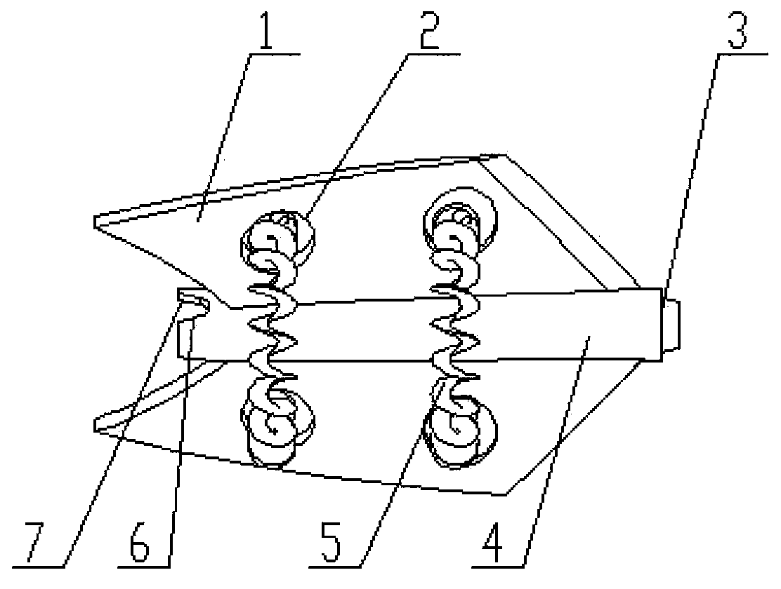
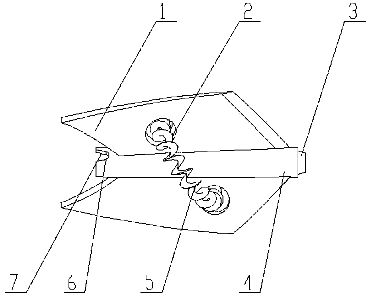
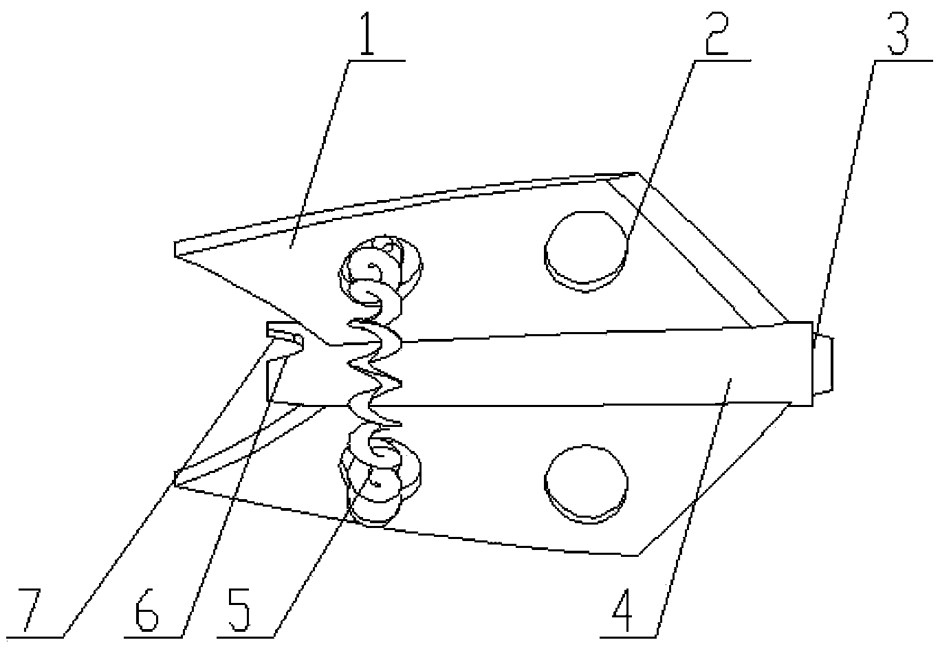
[0019] Such as Figure 4 As shown, the present invention relates to an implementation method of a perforated spring helical vane rotor in a heat exchange tube. The enhanced heat transfer device includes a rotor, a stopper 8, a heat exchange tube 9, a pendant 10 and a rotating shaft 11. Several rotors pass through The rotating shafts 11 are connected in series, and the limiting member 8 divides the plurality of rotors into several groups of rotor strings. The pendant 10 is fixed on both ends of the heat exchange tube 9, and the two ends of the rotating shaft 11 are respectively fixed on the pendant 10. The rotor of the present invention is composed of A certain number of perforated blades 1 are fixed on the surface of the hollow shaft 4. The surface of the blades is provided with a through hole 2 and a full coil spring 5 running through the through hole. The hollow shaft 4 is also provided with a ball socket boss 3, a ball Dimple platform 7 and hole 6 communicated with the inne...


PUM


Abstract

The invention relates to a through hole spring and helical blade rotor in a heat exchange tube. The rotor mainly consists of a hollow shaft, perforated blades and coil springs, the perforated blades are positioned on the surface of the hollow shaft, the outer diameter of each perforated blade is smaller than the inner diameter of the heat exchange tube, the perforated blades are smooth in surface and helically shaped around the hollow shaft, and through hole structures are arranged on the surface of each perforated blade so as to reduce contact area of fluid and the rotor blades and reduce pressure loss when the fluid flows through the rotor. The edge, firstly contacting with the fluid, of the perforated blades is chamfered or filleted, and holes communicating with an inner hole of the hollow shaft are evenly and circumferentially formed in the end, away from a water inlet, of the hollow shaft. The coil springs penetrate the through holes in the surfaces of the blades, in the process that the coil springs rotate with the rotor, radial movement of a fluid region between the blades is strengthened, and a turbulence effect of through hole regions is further improved; and impacts on a laminar boundary layer of heat transfer fluid nearby the tube wall are generated, so that effects of scale prevention, descaling and strengthened heat transfer are further realized.

Description

technical field [0001] The invention relates to an interpolation element for enhancing heat transfer and anti-fouling and decontamination in heat exchange tubes used in shell-and-tube heat exchangers, heat exchange reactors and other equipment, in particular to an interpolation element that uses the heat transfer fluid inside the heat exchange tube as the Power, low energy consumption and high efficiency perforated spring helical blade rotor that realizes self-cleaning and enhanced heat transfer function. Background technique [0002] Energy saving and emission reduction is a key technology that the whole world attaches great importance to. It is applied to many heat exchangers in many fields such as petroleum, chemical industry, thermal power, nuclear power, metallurgy, light industry, aviation devices and marine vehicles, among which the most Shell-and-tube heat exchangers are widely used, but there are common problems of fouling and fouling in the inner walls of these hea...

Claims


Application Information

Patent Timeline
Patent Type & Authority Applications(China)
IPC IPC(8): F28F9/24F28G3/00
Inventor 杨卫民张震关昌峰阎华焦志伟丁玉梅
Owner BEIJING UNIV OF CHEM TECH
Why Eureka
Try Eureka