
Method used for detecting +-pi/2 parameter of double-interference type fiber optic gyroscope based on optical path differencing operation

A fiber optic gyroscope and parameter measurement technology, which is applied to Sagnac effect gyroscopes and other directions, can solve the problems of decreased gyro sensitivity, affecting the practical application of gyroscopes, abnormal long-term output of differential double interferometric fiber optic gyroscopes, etc. The effect of a simple measurement process

Active Publication Date: 2013-11-27
BEIHANG UNIV
View PDF7 Cites 9 Cited by
  • Summary
  • Abstract
  • Description
  • Claims
  • Application Information

AI Technical Summary

Problems solved by technology

However, according to its modulation and demodulation principle, if there is an error in the measurement of the waveguide drive amplitude during ±π / 2 square wave modulation, the sensitivity of the gyro will decrease, and it will directly cause abnormalities in the long-term output of the differential double-interference fiber optic gyroscope. Seriously affect the practical application of gyro

Method used


Image

  • Method used for detecting +-pi/2 parameter of double-interference type fiber optic gyroscope based on optical path differencing operation
  • Method used for detecting +-pi/2 parameter of double-interference type fiber optic gyroscope based on optical path differencing operation
  • Method used for detecting +-pi/2 parameter of double-interference type fiber optic gyroscope based on optical path differencing operation

Examples


Embodiment Construction

[0023] The present invention will be further described in detail below in conjunction with the accompanying drawings.

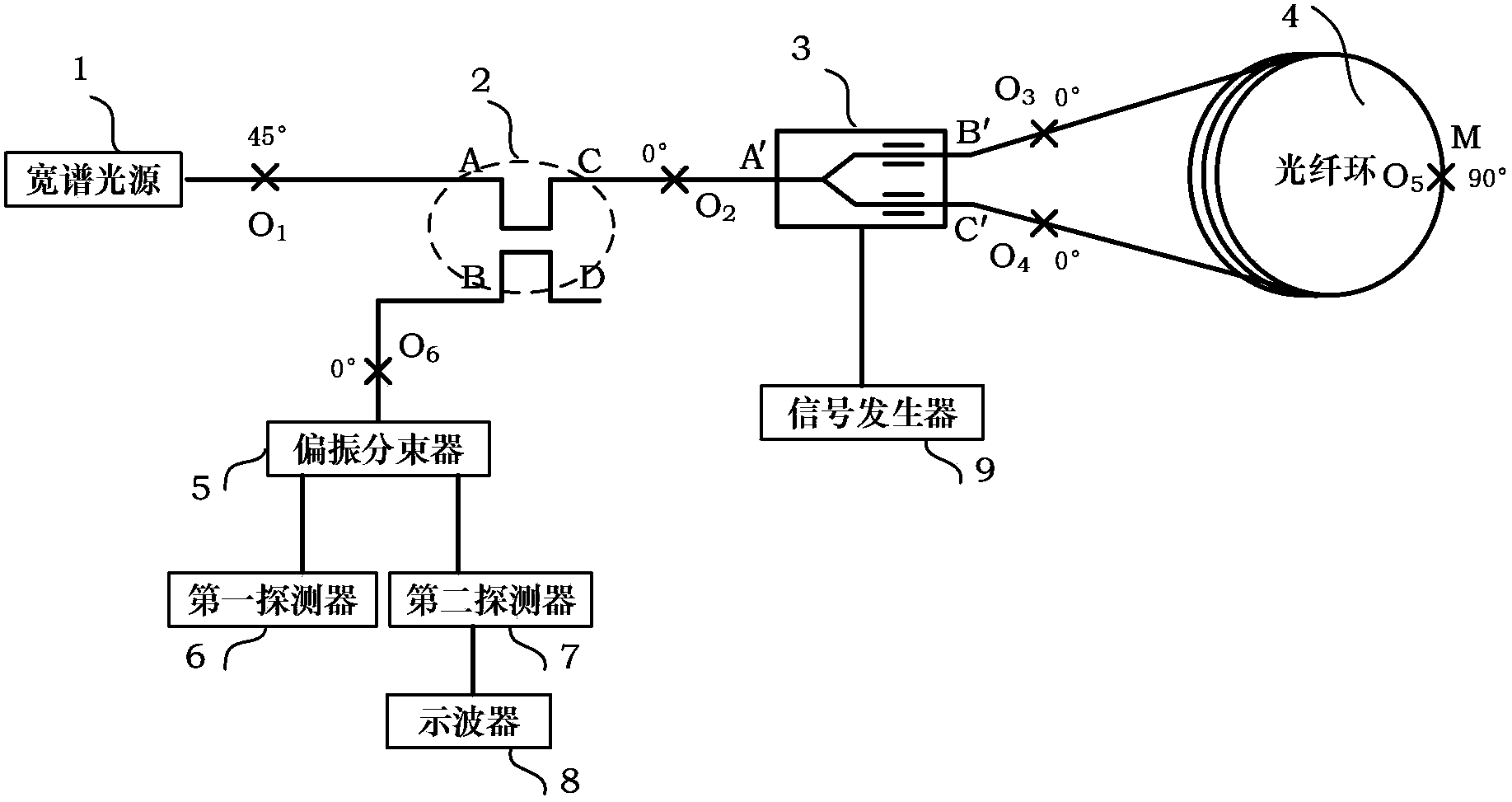
[0024] The present invention is a dual-interference optical fiber gyroscope ±π / 2 parameter measurement method based on optical path difference and its realization device. Its principle block diagram is as follows figure 1 As shown, the implementation device includes a light source 1, a coupler 2, a birefringent modulator 3, an optical fiber ring 4, a polarization beam splitter 5, a first detector 6, a second detector 7, an oscilloscope 8 and a signal generator 9 ;

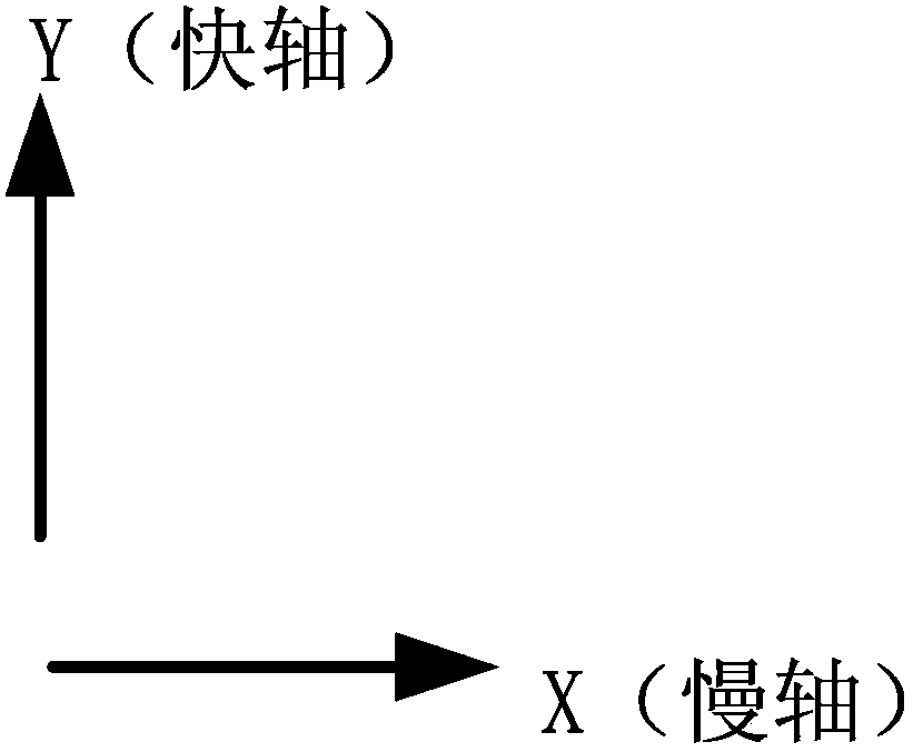
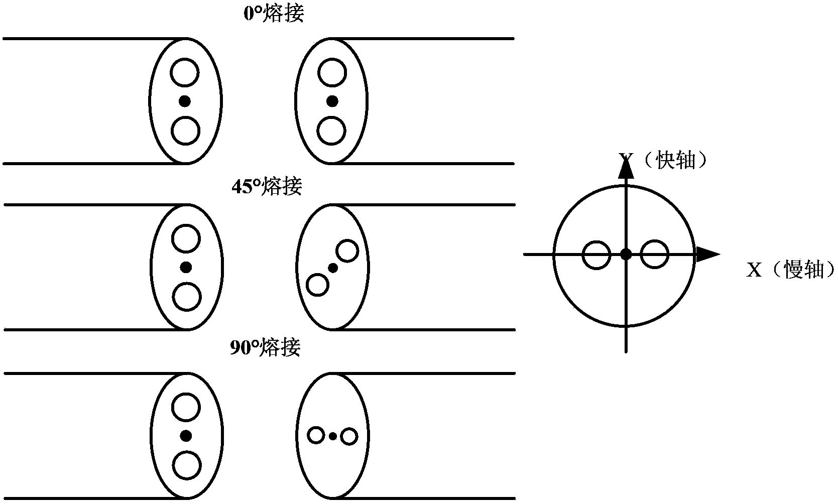
[0025] The coupler 2 has four ports, which are A terminal, B terminal, C terminal and D terminal respectively. The light source 1 and the A terminal of the coupler 2 are welded at 45° at the melting point O 1 , the C end of the coupler 2 and the A' end of the birefringent modulator 3 are welded at 0° at the melting point O 2 , the B'end and C'end of the birefringent modulator 3 are respectively ...


PUM


Abstract

The invention discloses a method used for detecting +-pi / 2 parameter of a double-interference type fiber optic gyroscope based on optical path differencing operation. The method comprises following steps: a polarized light wave output by a light source is subjected to 45 DEG cross coupling so as to generate two light waves with equal amplitudes and mutually-perpendicular polarization directions; the two light waves are input into a polarization maintaining optical fiber ring through a coupler and a birefringence modulator; a waveguide driving signal is generated by a single generator for the birefringence modulator, wherein the bias of the waveguide driving signal is 0, and the frequency of the waveguide driving signal is equal to the eigenfrequency of the polarization maintaining optical fiber ring; at the same time, the amplitude of the signal generated by the signal generator is adjusted, so that the output signal on a oscilloscope is identical with the output signal generated when the loop of the gyro is closed, wherein a modulated phase corresponding to the square wave amplitude generated by the signal generator is +-pi, and a voltage value corresponding to +-pi / 2 modulated phase is half of the square wave amplitude. The method is capable of realizing the detection of the +-pi / 2 parameter of the double-interference type fiber optic gyroscope based on optical path differencing operation, and avoiding sensitivity and precision reduction caused by the inaccuracy of the parameters. The method is simple in operation, and detection accuracy is high.

Description

technical field [0001] The invention belongs to the technical field of fiber optic gyroscopes, and relates to a method for measuring ±π / 2 parameters of a double-interference fiber optic gyroscope based on optical path difference. Background technique [0002] As a new type of inertial angular velocity sensor that is developing extremely rapidly, fiber optic gyroscope has its unique technical and performance advantages, such as all-solid-state structure, high reliability, long life; fast start-up speed, short response time; large measurement range and wide dynamic range ; Anti-shock, vibration, chemical corrosion resistance; small size, light weight, low cost; suitable for mass production, etc., have been widely used in various fields. [0003] The internationally accepted form of fiber optic gyroscope is the single interferometric type, that is, the fast axis or slow axis of a set of optical paths (a polarization-maintaining fiber ring) is used to realize the SAGNAC interfer...

Claims


Application Information

Patent Timeline
Patent Type & Authority Applications(China)
IPC IPC(8): G01C19/72
Inventor 徐小斌滕飞金靖宋凝芳张春熹张祖琛安明花
Owner BEIHANG UNIV
Learn More