Method for monitoring defects of high-temperature steam injection pipeline

A technology for steam injection pipes and defects, which is applied in the direction of analyzing solids using sound waves/ultrasonic waves/infrasonic waves, which can solve the problems of slow processing speed, complex structure, poor detection effect, etc., and meet the requirements of reducing smoothness, accurate defect positioning, and detection distance long effect

Active Publication Date: 2013-11-27
TSINGHUA UNIV
View PDF5 Cites 22 Cited by
  • Summary
  • Abstract
  • Description
  • Claims
  • Application Information

AI Technical Summary

Problems solved by technology

There are also equipments that use electromagnetic ultrasonic testing technology for defect detection at home and abroad. The patent application "Ultrasonic Guided Wave Inspection Method for Thick-walled Pipelines in Power Stations" with the application number 200910227225. Instead of using embedded probes, it cannot be applied to high-temperature in-service pipelines; the British PI company has developed the Teletest instrument, which is based on the principle of piezoelectric effect. When testing high-temperature pipelines with coatings, part of the coating must be removed to accommodate pressure. Electric sensors, and ensure that the surface of the pipeline is smooth and smooth, and the piezoelectric chip is not easy to adjust the guided wave mode; the MsS instrument developed by the Southwest Research Institute (SWRI) needs to attach a layer of magnetostrictive functional material-iron-cobalt strip to the surface of the pipeline The detection probe uses two probes to realize the transmission and reception of ultrasonic guided waves. This method has certain detection blind spots, poor de

Method used


Image

  • Method for monitoring defects of high-temperature steam injection pipeline
  • Method for monitoring defects of high-temperature steam injection pipeline
  • Method for monitoring defects of high-temperature steam injection pipeline

Examples


Embodiment Construction

[0031] The present invention will be described in detail below in conjunction with the accompanying drawings and embodiments.

[0032]A high-temperature steam injection pipeline defect monitoring method, comprising the following steps:

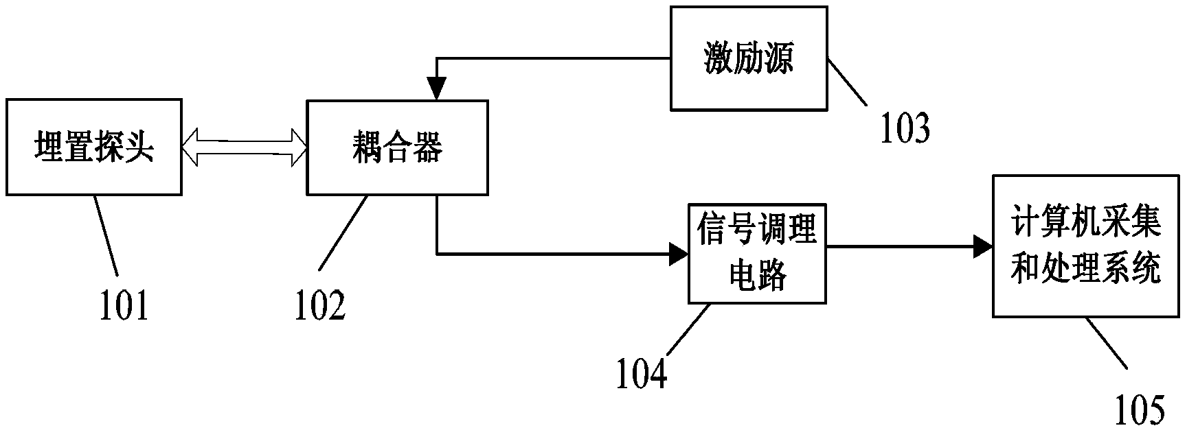
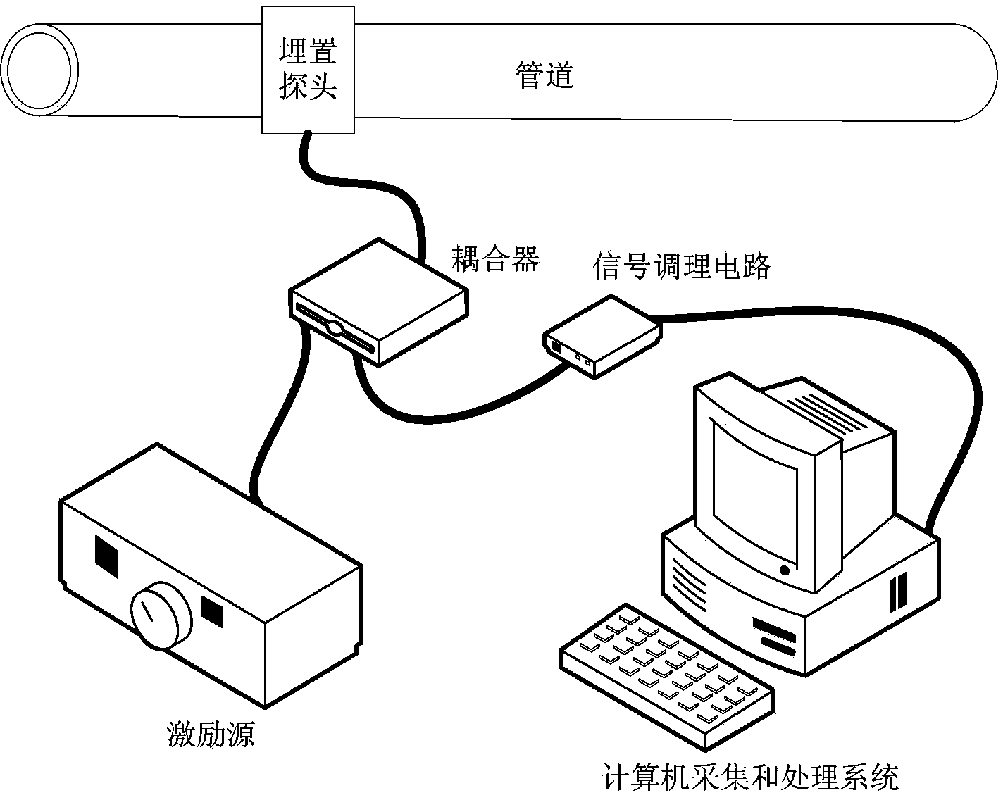
[0033] Step 1, the embedded probe 101 is connected to the probe interface of the coupler 102, and the excitation circuit 103 is connected to the excitation source interface of the coupler 102;

[0034] Step 2, the input end of the signal conditioning circuit 104 is connected to the signal conditioning interface of the coupler 102, and the output end is connected to the data acquisition card interface of the computer acquisition and processing system 105;

[0035] Step 3, the excitation source 103 inputs a pulse excitation signal to the embedded probe 101 through the coupler 102;

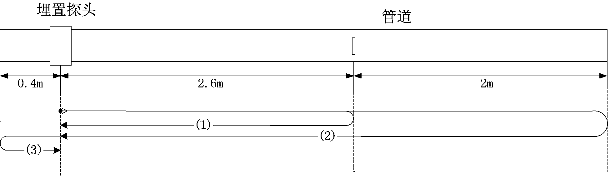
[0036] Step 4, the embedded probe 101 uses the magnetostrictive effect and Lorentz force of the pipeline material under the action of the bias magnetic field and th...


PUM


Abstract

The invention discloses a method for monitoring defects of a high-temperature steam injection pipeline. An embedded probe is connected with a probe interface of a coupler; an exciting circuit is connected with an excitation source interface of the coupler; an input end of a signal conditioning circuit is connected with a signal conditioning interface of the coupler, and an output end of the signal conditioning circuit is connected with a data acquisition card interface of a computer acquisition and processing system; the excitation source inputs a pulsed excitation signal to the embedded probe through the coupler, excites ultrasonic guided-waves in the pipeline, and generates ultrasonic echoes when encountering the defects, the ultrasonic echoes are transmitted to the embedded probe and are converted into voltage signals through the embedded probe; the voltage signals are transmitted to the signal conditioning circuit to be processed through the coupler and are output to the computer acquisition and processing system which acquires, processes and displays the ultrasonic echo signals containing defect information. The embedded probe can be embedded in an insulating layer of the pipeline, and the insulating layer of the high-temperature steam injection pipeline does not need to be damaged basically, but online detection and long-term monitoring for the defects of the pipeline can be realized, and the defects of the pipeline can be simply and accurately positioned.

Description

technical field [0001] The invention belongs to the technical field of ultrasonic guided wave non-destructive testing, and in particular provides a defect monitoring method for high-temperature steam injection pipelines. Background technique [0002] With the development of the national economy, the use of pipeline transportation is becoming more and more extensive. Pipeline transportation, together with railways, highways, aviation and water transportation, has become the five modern transportation industries. High-temperature steam injection pipelines are widely used in industries such as petroleum, chemical industry, metallurgy, natural gas, thermal power, nuclear power, and heat supply to transmit media such as oil, gas, and steam. Pipeline transportation is developing in the direction of high pressure, large diameter, and long distance. The working environment of the pipeline is becoming more and more complicated and harsh. Due to the use under high temperature and hig...

Claims


Application Information

Patent Timeline
IPC IPC(8): G01N29/07
Inventor 黄松岭赵伟王珅朱福荣魏争
Owner TSINGHUA UNIV
Why Eureka
Try Eureka