Dual dipole directional antenna fed by in-phase power divider

A double dipole and directional antenna technology, which is applied in the direction of antenna grounding switch structure connection, radiation element structure, etc., can solve complex structure and other problems, and achieve the effect of simple and compact structure, easy processing and good directional radiation characteristics

Inactive Publication Date: 2015-09-09
UNIV OF ELECTRONICS SCI & TECH OF CHINA
View PDF4 Cites 0 Cited by
  • Summary
  • Abstract
  • Description
  • Claims
  • Application Information

AI Technical Summary

Problems solved by technology

The double dipole antenna fed in reverse phase forms a W8JK structure, which can achieve directional radiation and can also effectively improve the antenna radiation gain, but it also requires a complex structure to achieve reverse feed

Method used


Image

  • Dual dipole directional antenna fed by in-phase power divider
  • Dual dipole directional antenna fed by in-phase power divider
  • Dual dipole directional antenna fed by in-phase power divider

Examples


Embodiment 1

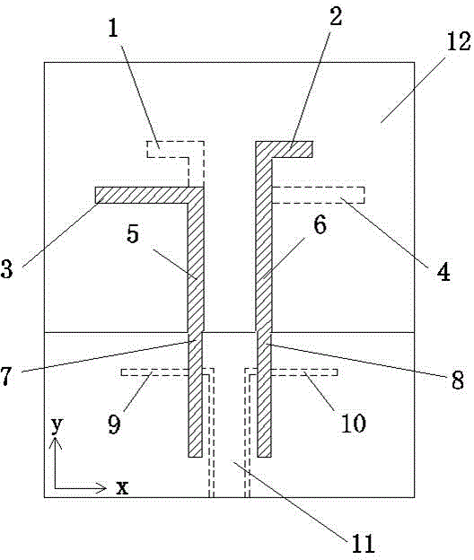
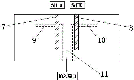
[0037] Such as figure 1 with image 3 As shown, based on the dual dipole directional antenna fed by the same-phase power divider, its radiation unit is a double dipole radiation unit composed of two printed dipoles printed on the dielectric substrate 12; its feed unit is In-phase power divider, the in-phase power divider is connected to the radiating unit through two parallel coupled double wires (the first parallel coupled double wire 5 and the second parallel coupled double wire 6).

[0038] The feeding unit includes a first microstrip feeder 7, a second microstrip feeder 8, a coplanar waveguide first slot line 9, a coplanar waveguide second slot line 10, and a coplanar waveguide feeder 11, wherein: the coplanar waveguide first The slot line 9 is coupled with the first microstrip feeder line 7 to form the first microstrip slot line conversion structure; the second slot line 10 of the coplanar waveguide is coupled with the second microstrip feeder line 8 to form the second m...

Embodiment 2

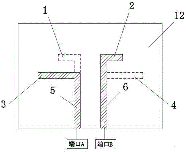
[0041] Such as figure 1 with figure 2 As shown, on the basis of Embodiment 1, the two printed dipoles of the dual-dipole directional antenna fed by the in-phase power divider in this embodiment are parallel to each other and have different lengths. The closer side of the long printed dipole. The long printed dipole has two vibrating arms: the first vibrating arm of the long printed dipole 3, the second vibrating arm of the long printed dipole 4; the short printed dipole also has two vibrating arms: the first vibrating arm of the short printed dipole 1 . The second vibration arm 2 of the short printed dipole, wherein: the first vibration arm 1 of the short printed dipole is printed on the reverse side of the dielectric substrate 12, and is connected with the metal strip on the reverse side of the first parallel coupled double line 5; the short printed dipole The second vibrating arm 2 is printed on the front of the dielectric substrate 12 and is connected to the front metal ...


PUM


Abstract

The invention discloses a double dipole directional antenna based on same-phase power divider feeding. The double dipole directional antenna comprises a dielectric substrate (12), a double dipole radiating unit, a feeding unit, a first parallel-coupled doublet (5) and a second parallel-coupled doublet (6), wherein the double dipole radiating unit is formed by two printing dipoles printed on the dielectric substrate (12), the feeding unit is a same-phase power divider, and an output port of the same-phase power divider is connected with the double dipole radiating unit through the first parallel-coupled doublet (5) and the second parallel-coupled doublet (6). According to the double dipole directional antenna, the same-phase power divider is adopted to feed the double dipole directional antenna needing reverse feeding, and the same-phase power divider is simple and compact in structure, small in size, light in weight, easy to machine, manufacture and integrate, and capable of reducing complexity of the structure of the antenna. The double dipole directional antenna based on same-phase power divider feeding has the advantages of directed radiation, a wide band, proper gain and the like.

Description

technical field [0001] The invention relates to a printed double dipole antenna, in particular to a double dipole directional antenna fed by an in-phase power divider. Background technique [0002] In recent years, wireless communication technology has been greatly developed and widely used. The antenna is an indispensable and important part of the wireless communication system, and its main purpose is to efficiently radiate and receive electromagnetic wave signals in a specific direction. Due to the development of wireless communication electronic equipment in the direction of multi-function and miniaturization, more and more communication systems require antennas that are low-cost, easy to manufacture, and easy to integrate with other microwave radio frequency planar circuits, and require antennas to have certain directional radiation characteristics , which makes the small antenna with wide frequency band, high gain and directional radiation become one of the hot researc...

Claims


Application Information

Patent Timeline
Patent Type & Authority Patents(China)
IPC IPC(8): H01Q1/38H01Q1/50
Inventor 赵志钦吴江牛王金叶宋健朱晓章
Owner UNIV OF ELECTRONICS SCI & TECH OF CHINA
Why Eureka
Try Eureka