
Annular high-speed voltage-controlled oscillator

A voltage-controlled oscillator and ring technology, applied in the direction of automatic power control, electrical components, etc., can solve the problems of small chip area, poor noise suppression ability, poor phase noise, etc., to achieve stable output swing, expand bandwidth, frequency improved effect

Active Publication Date: 2013-11-27
NANJING UNIV OF POSTS & TELECOMM INST AT NANJING CO LTD
View PDF3 Cites 8 Cited by
  • Summary
  • Abstract
  • Description
  • Claims
  • Application Information

AI Technical Summary

Problems solved by technology

[0005] Purpose of the invention: Aiming at the problems and deficiencies of the existing ring voltage-controlled oscillator, the purpose of the invention is to provide a ring voltage-controlled oscillator with high speed and high tuning linearity device

Method used

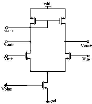
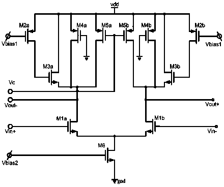
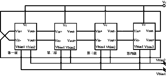

Image

  • Annular high-speed voltage-controlled oscillator
  • Annular high-speed voltage-controlled oscillator
  • Annular high-speed voltage-controlled oscillator

Examples


Embodiment Construction

[0020] In order to further illustrate the advantages of the present invention, the specific implementation manner and circuit structure of the present invention will be described in detail below in conjunction with the accompanying drawings.

[0021] The high-speed ring voltage-controlled oscillator of the present invention is composed of four stages of delay units in series, wherein the negative output terminal Vout- of each stage of delay unit is connected to the positive input terminal Vin+ of the next stage of delay unit, and the positive output of each stage of delay unit is The terminal Vout+ is connected to the negative input terminal Vin- of the next delay unit; the negative output terminal Vout- of the last delay unit is connected to the negative input terminal Vin- of the first delay unit, and the positive output terminal Vout+ of the last delay unit Connect to the positive input terminal Vin+ of the first-stage delay unit.

[0022] refer to figure 2 , the delay un...


PUM


Abstract

The invention discloses an annular high-speed voltage-controlled oscillator. The annular high-speed voltage-controlled oscillator is formed by series connection of four levels of delay units, wherein the negative output end (Vout-) of each level of delay unit is connected with the positive input end (Vin+) of a corresponding next level of delay unit, the positive output end (Vout+) of each level of delay unit is connected with the negative input end (Vin-) of a corresponding next level of delay unit, the negative output end (Vout-) of the last level of delay unit is connected with the negative input end (Vin-) of the first level of delay unit, and the positive output end (Vout+) the last level of delay unit is connected with the positive input end (Vin+) of the first level of delay unit. According to the annular high-speed voltage-controlled oscillator, an active electrical inductance structure is additionally arranged based on traditional delay units, a pair of PMOS tubes with grid electrodes connected to the ground are additionally arranged at a load end, therefore, oscillation of a circuit within the whole voltage range is guaranteed, extra electric currents can be provided for the circuit, and the oscillation frequency is improved; a control voltage is connected to the grid electrodes of the pair of PMOS tubes so that the frequency of the delay units can be controlled, and the PMOS tubes serve as voltage-controlled resistors and are used for adjusting the oscillating frequency.

Description

technical field [0001] The invention belongs to the field of semiconductor integrated circuit design, and mainly relates to a ring voltage-controlled oscillator with high speed and high tuning linearity. Background technique [0002] A voltage-controlled oscillator (Voltage-Controlled-Oscillator, VCO) is a signal source whose frequency varies with voltage. It is widely used in phase-locked loops, clock recovery and frequency synthesis circuits, and is a key component of these circuits. In integrated circuits, voltage-controlled oscillators can be divided into two categories: ring oscillators and inductor-capacitor oscillators. The noise performance of the LC oscillator is better, but it requires an additional process to integrate the inductor and occupies a larger area. The ring oscillator can be realized by standard CMOS technology, relatively small in area, and has a wide tuning range, which is suitable for system-on-chip. [0003] Ring oscillators can be divided into t...

Claims


Application Information

Patent Timeline
IPC IPC(8): H03L7/099
Inventor 张长春房军梁陈德媛郭宇锋方玉明
Owner NANJING UNIV OF POSTS & TELECOMM INST AT NANJING CO LTD
Learn More