Centrifuging device and sludge dehydrating method

A technology for centrifugal separation and sludge, applied in centrifuges, centrifuges with rotating drums, dewatering/drying/concentrating sludge treatment, etc., to achieve the effect of low moisture content

Inactive Publication Date: 2013-12-04
TOMOE ENGINEERING CO LTD
View PDF5 Cites 12 Cited by
  • Summary
  • Abstract
  • Description
  • Claims
  • Application Information

AI Technical Summary

Problems solved by technology

However, in the prior art disclosed in Patent Documents 1-3, there is still room for improvement regarding the method of adding t...

Method used


Image

  • Centrifuging device and sludge dehydrating method
  • Centrifuging device and sludge dehydrating method
  • Centrifuging device and sludge dehydrating method

Examples


no. 1 approach )

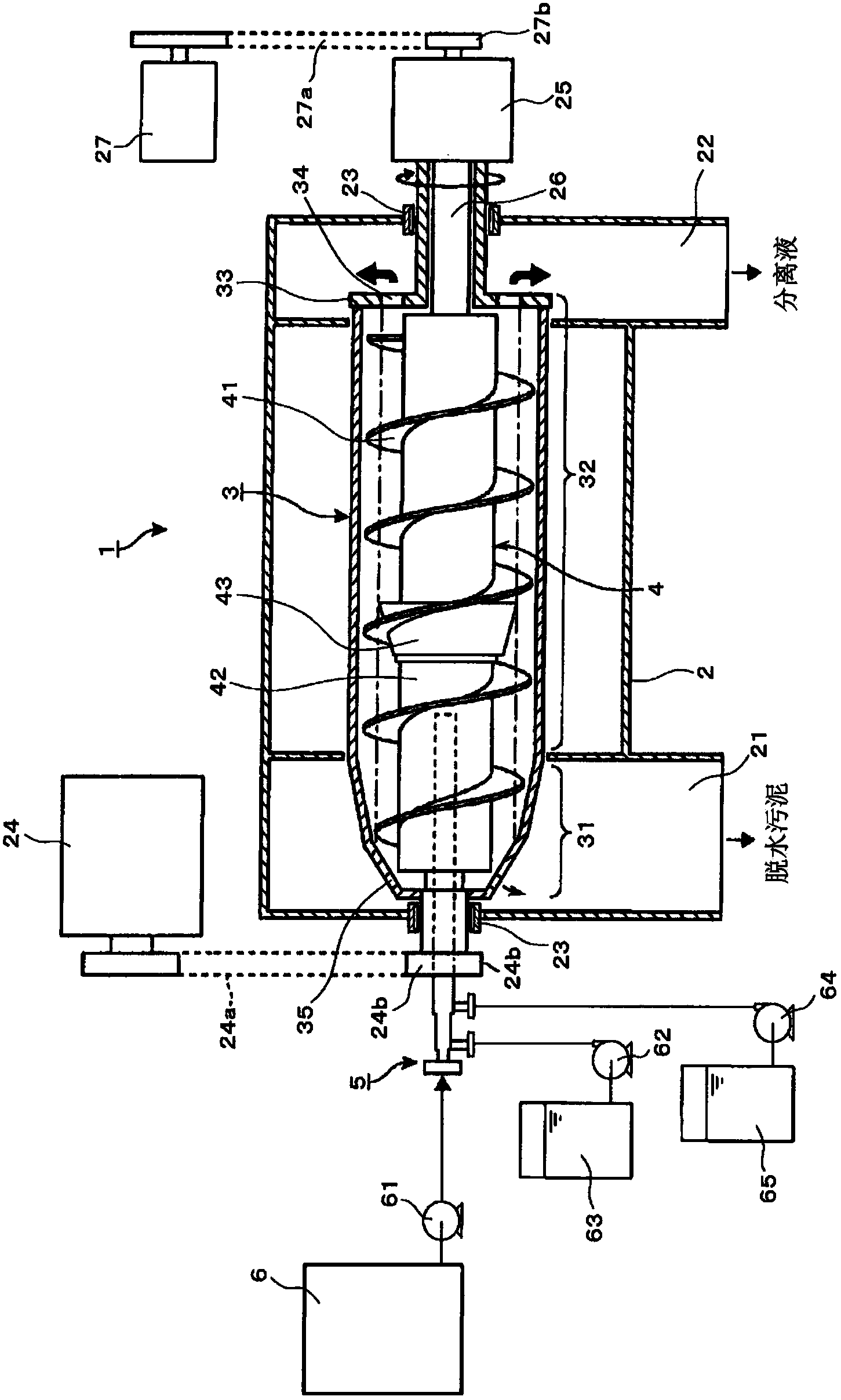
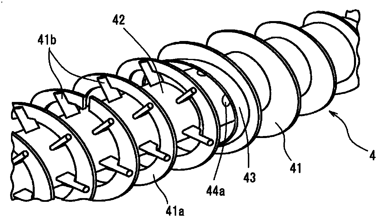
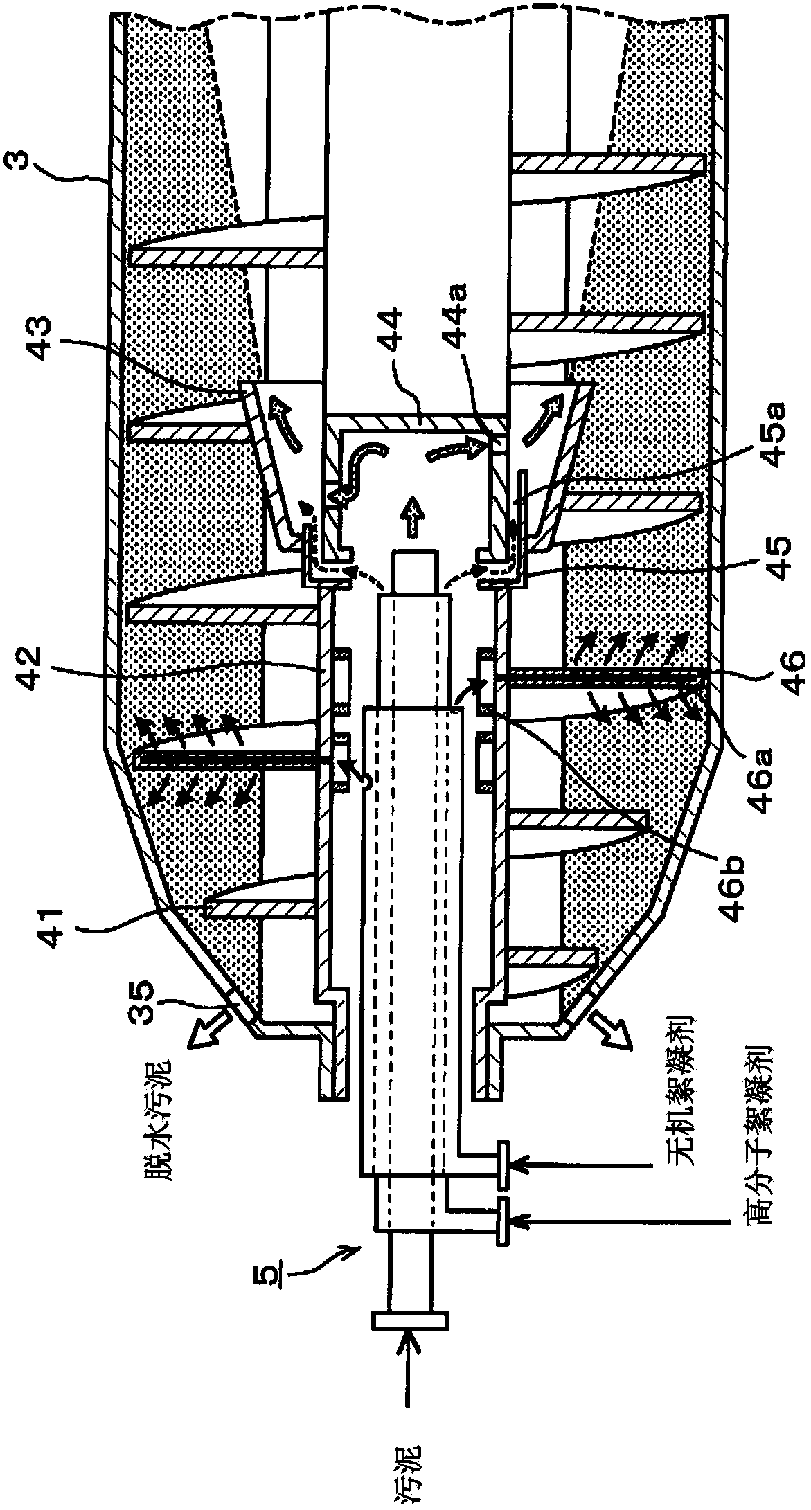
[0049] Taking a horizontal decanter as an example, the centrifugal separation device according to the first embodiment of the present invention will be described. like figure 1 As shown, the decanter 1 of this embodiment includes: a housing 2 with a dewatered sludge outlet 21 and a separation liquid outlet 22 respectively formed below; a drum 3 arranged in the housing 2 and formed as a drum; And the screw conveyor 4 as a conveying unit of the separated sludge in the drum 3 . The cylinder 3 is supported by a bearing structure 23 such as a bearing attached to the casing 2, and the screw conveyor 4 is supported by a conveyor bearing (not shown), and the cylinder 3 and the screw conveyor 4 are each independently rotatable around a horizontal axis.

[0050] The power of the driving motor 24 as the driving structure is transmitted to the pulley 24b on the side of the cylinder 3 through the transmission belt 24a, so that the cylinder 3 rotates at a certain rotational speed, and the ...

no. 2 approach )

[0077] Next, a horizontal decanter will be described as an example of a centrifugal separator according to a second embodiment of the present invention. like Figure 6 As shown, the decanter 1 of the present embodiment is provided with a new disk-shaped member 7 as a member for adding an inorganic flocculant, which is different from the first embodiment in which the screw blade 41 also serves as a member for adding an inorganic flocculant. Other structures may be the same as those of the first embodiment. Therefore, the same structures are assigned the same reference numerals, and detailed description thereof will be omitted.

[0078] The disc-shaped member 7 as an adding member is a disc-shaped member, and is provided on the outer periphery of the main body portion 42 of the screw conveyor 4 so as to be concentric with the rotation shaft. The disk-shaped member 7 is the same as the helical blade 41 of the first embodiment, and has a hollow structure inside, and forms the fl...

no. 3 approach )

[0081] Next, a horizontal decanter will be described as an example of a centrifugal separator according to a third embodiment of the present invention. like Figure 7 As shown, the decanter 1 of this embodiment differs from the second embodiment in that a nozzle member 8 is provided instead of the disk member 7 . Other structures may be the same as those of the first and second embodiments. Therefore, the same structures are assigned the same reference numerals, and detailed description thereof will be omitted.

[0082] The nozzle member 8 as an adding member is, for example, a pipe whose cross section is circular (see the cross-sectional view), and extends radially from the main body portion 42 of the screw conveyor 4 . The nozzle members 8 may not only be arranged in two phases of 0° and 180°, but may also be arranged in only one phase. Alternatively, they may also be arranged radially (for example, at intervals of 90°) along the radial direction of the screw conveyor 4 ....


PUM


Abstract

A polymer flocculant and an inorganic flocculant are added in sludge dehydration as dehydration assistants, and the inorganic flocculant is uniformly dispersed in sludge to improve the dehydration efficiency. A centrifuging device disclosed in the invention is characterized in that the centrifuging device comprises: a rotating cylinder having a hollow cylinder portion and used for separating the sludge into dehydrated sludge and a separation liquid through utilizing the centrifuging force; a screw conveyer arranged in the rotating cylinder to rotate relative to the rotating cylinder in a relative rotating speed difference mode; a unit for supplying the sludge into the rotating cylinder; a first flocculant adding unit for adding a first flocculant into the sludge supplied into the rotating cylinder; and a second flocculant adding unit for adding a second flocculant to the sludge conveyed to the outlet of the dehydrated sludge formed in the rotating cylinder by the screw conveyer, wherein the second flocculant adding unit has an adding part partially or fully dipped in the sludge in the rotating cylinder, and the outlet of the second flocculant is arranged at the position of the part dipped in the sludge.

Description

technical field [0001] The invention relates to a centrifugal separation device and a sludge dewatering method, in particular to a centrifugal separation device and a sludge dehydration method for adding a flocculant as a dehydration aid to dewater sludge. Background technique [0002] Sludge generated during water treatment such as sewage, industrial effluent, human waste, etc. can be dewatered using a centrifugal separation device called a decanter. [0003] The decanter has a casing, a cylinder rotating around a horizontal axis in the casing, an auger accommodated in the casing, and a drive motor provided outside the casing. The decanter supplies sludge to the rotating drum, and uses centrifugal force to separate water from the sludge. At this time, the screw conveyor is rotated using a speed difference generating device such as a transmission, and the dewatered sludge is sent to a discharge port formed in the conical portion of the cylinder to be discharged. On the oth...

Claims


Application Information

Patent Timeline
IPC IPC(8): C02F11/12B04B1/20
Inventor 平松达生
Owner TOMOE ENGINEERING CO LTD
Why Eureka
Try Eureka