
Pallet and plasma processing equipment for induction heating

An induction heating and tray technology, applied in induction heating, induction heating device, metal material coating process, etc., can solve the problems of increasing the temperature difference between the edge area and the center area, reducing the temperature, and increasing the amount of heat and heat, so as to improve the uniformity of the process. The effect of reducing the temperature difference and uniform distribution density

Inactive Publication Date: 2013-12-04
BEIJING NAURA MICROELECTRONICS EQUIP CO LTD
View PDF4 Cites 2 Cited by
  • Summary
  • Abstract
  • Description
  • Claims
  • Application Information

AI Technical Summary

Problems solved by technology

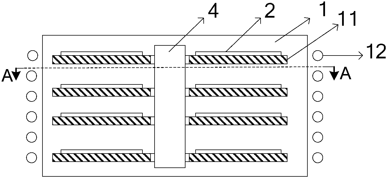
[0004] In the process of using the induction coil 12 to heat the processed workpiece 2, due to the skin effect of induction heating, the distribution density of the eddy current induced in the edge area of ​​the tray 11 is greater than the distribution density of the eddy current induced in the central area, which makes The heat generated in the edge area of ​​the tray 11 is more than that in the center area, thus causing the temperature in the edge area of ​​the tray 11 to be higher than the temperature in the center area, thereby causing a temperature difference between the edge area and the center area of ​​the processed workpiece 2
[0005] In addition, because the reaction gas is ejected from the gas outlet close to the central area of ​​the workpiece 2, and the temperature of the reactant gas just ejected is lower than the internal temperature of the reaction chamber 1, resulting in the temperature of the central area of ​​the workpiece 2 It will be reduced due to the heat absorbed by the reaction gas, which further increases the temperature difference between the edge area and the central area of ​​the processed workpiece 2, thereby reducing the process uniformity

Method used


Image

  • Pallet and plasma processing equipment for induction heating
  • Pallet and plasma processing equipment for induction heating
  • Pallet and plasma processing equipment for induction heating

Examples


Embodiment Construction

[0031] In order for those skilled in the art to better understand the technical solution of the present invention, the tray for induction heating and the plasma processing equipment provided by the present invention will be described in detail below with reference to the accompanying drawings.

[0032] For the convenience of description, in the following embodiments, the tray used for induction heating is placed horizontally as the reference plane, and the upper surface and the lower surface of the tray body refer to the upward surface and the downward surface of the tray body respectively.

[0033] Figure 3a A cross-sectional view of the tray for induction heating provided by the first embodiment of the present invention.

[0034] Figure 3b for Figure 3a Top view of the tray shown. Please also refer to Figure 3a with Figure 3b , the tray used for induction heating includes a tray body 30 made of magnetically conductive material, which is made of high temperature res...


PUM


Abstract

The invention provides a pallet for induction heating. The pallet comprises a pallet body made of a magnetic conductive material, and is characterized in that a plurality of adjusting parts are arranged at the circumferential direction of the pallet body at intervals; and the adjusting parts are used for guiding eddy current in the edge area of the pallet body and generated by electromagnetic induction to a central area of the pallet body. The pallet for induction heating provided by the invention can uniformly heat the workpiece to be processed, thereby increasing technical uniformity of the workpiece to be processed.

Description

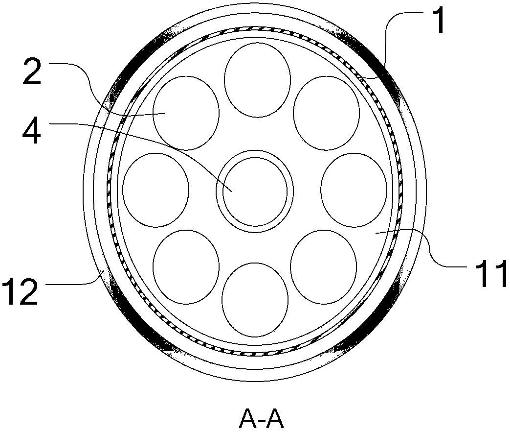
technical field [0001] The invention relates to the technical field of microelectronic processing, in particular to a tray for induction heating and plasma processing equipment using the tray. Background technique [0002] The principle of using metal organic chemical vapor deposition (Metal Organic Chemical Vapor Deposition, hereinafter referred to as MOCVD) equipment to prepare thin films is to mix the metal organic compound of group II or III with the hydride of group IV or V element and then pass it into the reaction chamber. The mixed gas undergoes a thermal decomposition reaction on the heated substrate surface, and epitaxially grows on the substrate surface to form a thin film. [0003] figure 1 It is a schematic diagram of the structure of MOCVD equipment. figure 2 for along figure 1 Sectional view of line A-A in middle. Please also refer to figure 1 with figure 2 , the MOCVD equipment includes a reaction chamber 1, in the reaction chamber 1 there are vertica...

Claims


Application Information

Patent Timeline
Patent Type & Authority Applications(China)
IPC IPC(8): C23C16/46H05B6/10
Inventor 董志清张秀川
Owner BEIJING NAURA MICROELECTRONICS EQUIP CO LTD
Learn More