
Gas burner

A gas burner and a burner technology, which are applied in the directions of burners, gas fuel burners, combustion methods, etc., can solve the problem that it is difficult to meet the natural stratification law of bottled liquefied petroleum gas, uneven aeration without a head channel, and difficult to meet the Gas source instability and other problems, to achieve the effect of reducing mutual interference, stabilizing firepower, and reasonable structure

Active Publication Date: 2013-12-04
MARSSENGER KITCHENWARE CO LTD
View PDF5 Cites 25 Cited by
  • Summary
  • Abstract
  • Description
  • Claims
  • Application Information

AI Technical Summary

Problems solved by technology

Its disadvantage is that there is no head channel and the gas mixture is uneven, which can easily cause yellow flames and flame separation. The reason is that the premixed primary air before combustion of the gas must be uniformly mixed with the gas, so that the flame can burn stably, and the uneven mixing will cause excessive gas. The fire hole of the smoked pot produces a yellow flame, and the smoke pot, the fire hole with less gas and more air, produces a flame, and the adaptability is poor. It is difficult to meet the unstable gas source in the Chinese market, and it is also difficult to satisfy the bottled liquefied petroleum gas from the full bottle to the bottom bottle. The law of natural stratification of air

Method used


Image

  • Gas burner
  • Gas burner
  • Gas burner

Examples


Embodiment Construction

[0030] Now in conjunction with accompanying drawing, the present invention will be further described:

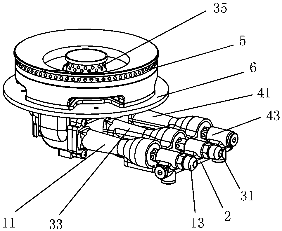
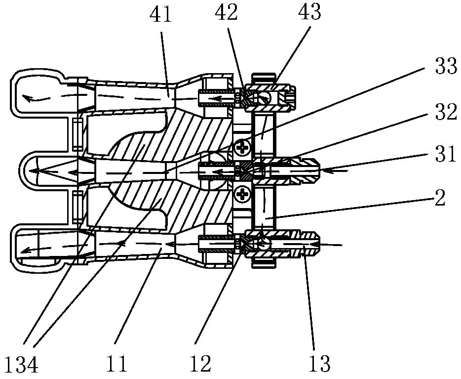
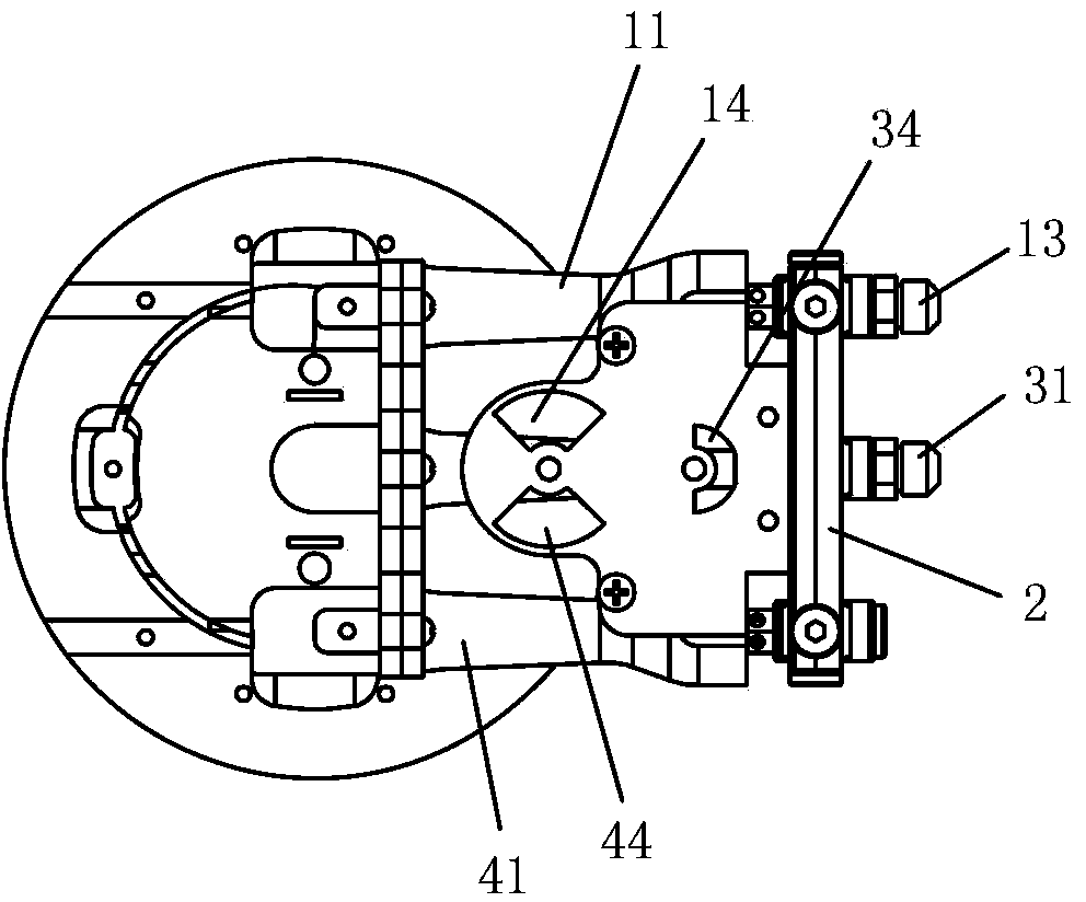
[0031] A gas burner, comprising an injection tube assembly, a burner base 6, an outer ring burner 5 and an inner ring burner 35;

[0032] Injection tube assembly includes:

[0033] The gas pipe sub-joint 31, sub-nozzle 32, and sub-injection pipe 33 communicated with the gas pipe are connected in sequence, and the sub-injection pipe 33 is also communicated with the auxiliary primary air inlet 34;

[0034] The first air pipe main joint 13, the first main nozzle 12, and the first main ejector pipe 11 communicated with the gas pipe, and communicated in sequence, and the first main ejector pipe 11 is also communicated with the first main primary air inlet 14;

[0035] The second air pipe main joint 43, the second main nozzle 42 and the second main injection pipe 41 are communicated in sequence, and the second main ejection pipe 41 is also communicated with the second main primar...


PUM


Abstract

The invention discloses a gas burner which comprises an ejector tube assembly, a burner base, an outer ring burner body and an inner ring burner body. The ejector tube assembly comprises auxiliary gas pipe connectors, auxiliary nozzles, auxiliary ejector tubes, first main gas pipe connectors, first main nozzles, first main ejector tubes, second main gas pipe connectors, second main nozzles and second main ejector tubes. The auxiliary gas pipe connectors, the auxiliary nozzles and the auxiliary ejector tubes are communicated with gas pipes, each auxiliary gas pipe connector, each auxiliary nozzle and each auxiliary ejector tube are sequentially communicated with one another, and the auxiliary ejector tubes are further communicated with a primary air inlet. The first main gas pipe connectors, the first main nozzles and the first main ejector tubes are communicated with the gas pipes, each first main gas pipe connector, each first main nozzle and each first main ejector tube are sequentially communicated with one another, and the first main ejector tubes are further communicated with a first main primary air inlet. Each second main gas pipe connector, each second main nozzle and each second main ejector tube are sequentially communicated with one another, the second main ejector tubes are further communicated with a second main primary air inlet, and the second main gas pipe connectors are communicated with the first main gas pipe connectors through main gas ducts and branch gas ducts. The outer ring burner body comprises an outer ring base and an outer ring fire cover, and two symmetrical gas mixing chambers are formed. The gas burner has the advantages of being reasonable in structure, small in airflow resistance, sufficient in combustion, high in thermal efficiency and little in discharged waste gas.

Description

technical field [0001] The invention relates to a gas burner. Background technique [0002] The combustion system is the core component of the cooker module. Using a burner with complete combustion, high efficiency and stable performance can greatly improve the performance of the entire cooker. Therefore, designing a burner with high efficiency and stable performance is a high-tech problem in the stove industry. [0003] In the prior art, the common practice of gas stoves is as follows: first, the outer ring fire uses a single nozzle and a single injection pipe, and the gas ejected by the single nozzle ejects the primary air into the gas mixing chamber and is distributed to the outer ring fire cover through the gas distribution channel. One week, it burns through the fire hole. The disadvantage is that the ejector tube is large and long, and the diameter of the head channel is large, which is easy to cause flashback and flameout pop. The reason is that when the gas burns in...

Claims


Application Information

Patent Timeline
IPC IPC(8): F23D14/06F23D14/64F23D14/46
Inventor 李欣黄安奎黄卫斌
Owner MARSSENGER KITCHENWARE CO LTD
Features
  • Generate Ideas
  • Intellectual Property
  • Life Sciences
  • Materials
  • Tech Scout
  • Unparalleled Data Quality
  • Higher Quality Content
  • 60% Fewer Hallucinations
Learn More